O.a.l. Gauge
O.a.l. Gauge
In the field of industrial process control, accurate liquid level measurement is a fundamental requirement for safety, efficiency, and inventory management. Among the various technologies available, Magnetic & Local Level Gauges remain a cornerstone for visual monitoring in tanks and pressure vessels. A critical specification in the procurement and engineering of these instruments is the o.a.l. gauge (Overall Length gauge) dimension. Understanding the relationship between the measuring range, the center-to-center distance, and the total physical footprint of the device is essential for successful integration into complex piping systems.
Measurement Principles of Magnetic Level Gauges
Before selecting a specific o.a.l. gauge configuration, it is necessary to understand the underlying physics of magnetic level measurement. These instruments operate on the principles of buoyancy and magnetism to provide a clear, local indication of liquid levels without the risks associated with direct-contact glass gauges.
The Buoyancy Principle
A magnetic level gauge consists of a bypass chamber (typically a vertical pipe) connected to the side of a vessel. Inside this chamber is a float specifically engineered to match the density (specific gravity) of the process fluid. According to Archimedes' principle, the float will remain partially submerged and rise or fall precisely with the liquid level in the vessel.
Magnetic Coupling
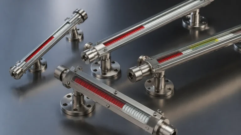
The float contains a high-intensity internal magnet assembly. Outside the chamber, a visual indicator—often consisting of bi-color magnetic flaps or a magnetic follower—is mounted. As the float moves, its magnetic field penetrates the non-magnetic chamber wall (usually stainless steel or plastic), causing the external flaps to rotate or the follower to move. This provides a high-visibility representation of the liquid level that is completely isolated from the process pressure and temperature.
Defining the O.a.l. Gauge Dimension
In technical drawings and procurement specifications, the term "o.a.l. gauge" refers to the total vertical height of the instrument from the topmost point to the bottommost point. This is distinct from the "Measuring Range" or the "Center-to-Center" (C-C) distance.
1. Measuring Range: This is the actual distance over which the level can be detected. It is determined by the travel of the float.
2. Center-to-Center (C-C): This is the distance between the centerlines of the top and bottom process connections. This dimension must match the nozzle spacing on the vessel.
3. Overall Length (OAL): The o.a.l. gauge dimension includes the C-C distance plus the additional length required for the "dead zones" at the top and bottom of the chamber. The bottom section must be long enough to house the float when the tank is empty, and the top section must accommodate the float when the tank is full, ensuring the magnetic assembly remains aligned with the indicator.
For engineers, the OAL is the most critical dimension for physical clearance. If a tank is located in a room with a low ceiling or if there are structural beams near the vessel nozzles, a gauge with an excessive OAL may not fit, even if the C-C distance is correct.
Selection Criteria for Magnetic & Local Level Gauges
Selecting the correct instrument requires a detailed analysis of the application environment. Welk provides a range of materials and configurations to suit different industrial needs. The following table summarizes the primary selection factors:
| Parameter | Consideration | Typical Options |
| :— | :— | :— |
| Chamber Material | Chemical compatibility and pressure rating | 304/316L Stainless Steel, PVC, PP, PVDF, Titanium |
| Pressure Rating | Maximum operating and design pressure | Vacuum to 25 MPa (approx. 250 bar / 3600 psi) |
| Temperature Range | Impact on float magnetism and indicator materials | -196°C to +450°C |
| Fluid Density | Must be higher than the float's minimum buoyancy | 0.45 g/cm³ to 2.0 g/cm³ |
| Viscosity | High viscosity can impede float movement | Up to 500 cP (special floats for higher) |
| Connection Type | Matching vessel nozzles | Flanged (ANSI/DIN), Threaded (NPT/G), Welded |
When specifying an o.a.l. gauge, users must ensure the float material can withstand the process pressure without collapsing. For high-pressure applications, titanium floats are often preferred over stainless steel due to their superior strength-to-weight ratio.
Installation Considerations and Best Practices
Correct installation is paramount to ensuring the accuracy and longevity of Magnetic & Local Level Gauges. Because these are mechanical-magnetic systems, physical alignment and environmental factors play a significant role.
Vertical Alignment
The bypass chamber must be installed perfectly vertical. Even a slight tilt can increase friction between the float and the chamber wall, leading to "sticking" or erratic readings. Use a spirit level or plumb line during installation to verify verticality within ±0.5 degrees.
Magnetic Interference
Since the device relies on magnetic coupling, it must be kept away from large ferrous structures or strong electromagnetic fields. External steel supports should be positioned at a minimum distance (typically 100 mm or 4 inches) from the chamber to prevent magnetic drag on the float.
Venting and Draining
Standard o.a.l. gauge designs include a vent plug at the top and a drain plug or valve at the bottom. These are essential for commissioning and maintenance. Before startup, the chamber should be vented to ensure there are no air pockets that could prevent the liquid from entering the chamber at the correct level.
Insulation
In high-temperature or cryogenic applications, the chamber may require insulation to maintain the fluid's state or protect personnel. However, the visual indicator must remain outside the insulation or be equipped with a frost-extending window to remain readable.
Limitations and Operational Boundaries
While highly versatile, magnetic level gauges have specific limitations that must be acknowledged during the engineering phase:
* Particulate Matter: If the process fluid contains magnetic particles (such as iron filings or scale), these can adhere to the float's magnet, increasing its weight and eventually jamming it against the chamber wall. Magnetic filters or traps should be installed in the bypass lines in such cases.
* Coating and Scaling: Fluids that tend to crystallize or leave heavy deposits can coat the float and the interior of the chamber. This changes the float's buoyancy and increases mechanical friction. Regular flushing via the drain valve is required for these services.
* Specific Gravity Fluctuations: The float is weighted for a specific density. If the process involves different fluids or significant temperature swings that change the liquid's density, the float may sit higher or lower in the liquid, introducing a small measurement error.
* Mechanical Shock: High-velocity fluid entry during tank filling can cause the float to slam into the top of the chamber, potentially damaging the magnet or the float structure. Stilling wells or restricted orifice plates in the connection lines can mitigate this risk.
Technical Comparison: Magnetic vs. Traditional Glass Gauges
| Feature | Magnetic Level Gauge | Reflex/Transparent Glass Gauge |
| :— | :— | :— |
| Safety | High (No glass to break, no leaks) | Moderate (Risk of glass shattering) |
| Visibility | Excellent (Visible from 30m+) | Limited (Requires close proximity) |
| Maintenance | Low (Occasional flushing) | High (Cleaning glass, replacing gaskets) |
| Pressure Limits | Very High | Limited by glass thickness |
| Cost | Higher initial investment | Lower initial investment |
Frequently Asked Questions (FAQs)
Q: How do I determine the required o.a.l. gauge for my tank?
A: Start with the center-to-center distance of your vessel nozzles. Add the manufacturer's required "top extension" and "bottom extension" (typically 150 mm to 300 mm each, depending on float size). This sum is your OAL. Always check the manufacturer's data sheet for the specific float length required for your fluid density.
Q: Can I use a magnetic level gauge for interface measurement (e.g., oil and water)?
A: Yes. By using a float weighted to a density between the two liquids (e.g., 0.85 g/cm³), the float will sink through the upper liquid and float on the lower liquid, providing a clear indication of the interface level.
Q: What happens if the float is installed upside down?
A: The gauge will not function correctly. Most floats are marked with a "TOP" arrow. If installed upside down, the center of the magnetic field will not align with the zero point of the indicator, and the buoyancy characteristics will be incorrect.
Q: Are these gauges suitable for high-vibration environments?
A: Yes, but it is recommended to use an indicator with "damped" flaps or a magnetic follower system designed for vibration. Additionally, the chamber should be securely braced to the vessel or nearby structural steel.
Q: Can I add electronic output to a local level gauge?
A: Absolutely. One of the primary advantages of the magnetic design is that a reed-switch transmitter or a magnetostrictive sensor can be clamped to the outside of the chamber. This allows for 4-20mA, HART, or Modbus output to a PLC/DCS without additional tank penetrations.
Conclusion
The o.a.l. gauge dimension is more than just a measurement; it is a critical integration parameter that ensures a level instrument fits and functions within its intended environment. By prioritizing the measurement principles of buoyancy and magnetism, and carefully selecting materials based on pressure, temperature, and density, engineers can implement Magnetic & Local Level Gauges that provide decades of reliable service. Whether for simple water storage or high-pressure chemical reactors, the clarity and safety of a well-specified local indicator remain unmatched in the industrial sector.