3 4 Level Gauge
3 4 Level Gauge
In industrial process control, the ability to monitor liquid levels locally and accurately is fundamental to safety and operational efficiency. Among the various configurations available, the 3 4 level gauge—referring to instruments with a 3/4-inch NPT or flanged connection—stands as one of the most common specifications in piping and vessel design. These gauges, particularly Magnetic & Local Level Gauges, provide a robust alternative to traditional glass gauges, offering enhanced safety in high-pressure or corrosive environments.
Selecting the correct 3/4-inch level gauge requires an understanding of the underlying measurement principles, material compatibility, and the specific mechanical requirements of the process vessel. This guide explores the technical aspects of these instruments, focusing on their application in modern industrial automation.
Measurement Principles of Magnetic Level Gauges
Before selecting a 3 4 level gauge, it is essential to understand how magnetic level indicators function. Unlike standard tubular glass gauges that rely on direct visual contact with the process fluid, magnetic gauges utilize a magnetic coupling system to isolate the indicator from the medium.
The Float and Chamber System
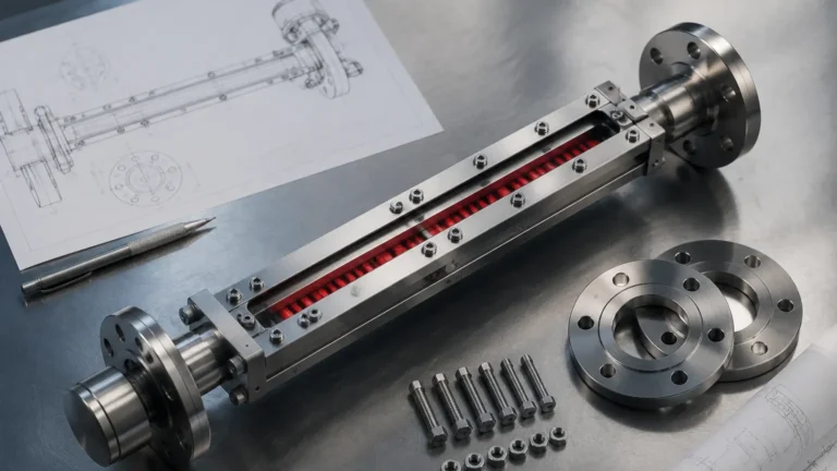
The system consists of a vertical chamber (typically 2-inch or 2.5-inch pipe) connected to the side of the tank via 3/4-inch process connections. Inside this chamber is a float specifically engineered to match the specific gravity (SG) of the liquid being measured. This float contains a high-intensity permanent magnet assembly.
The Indicator Assembly
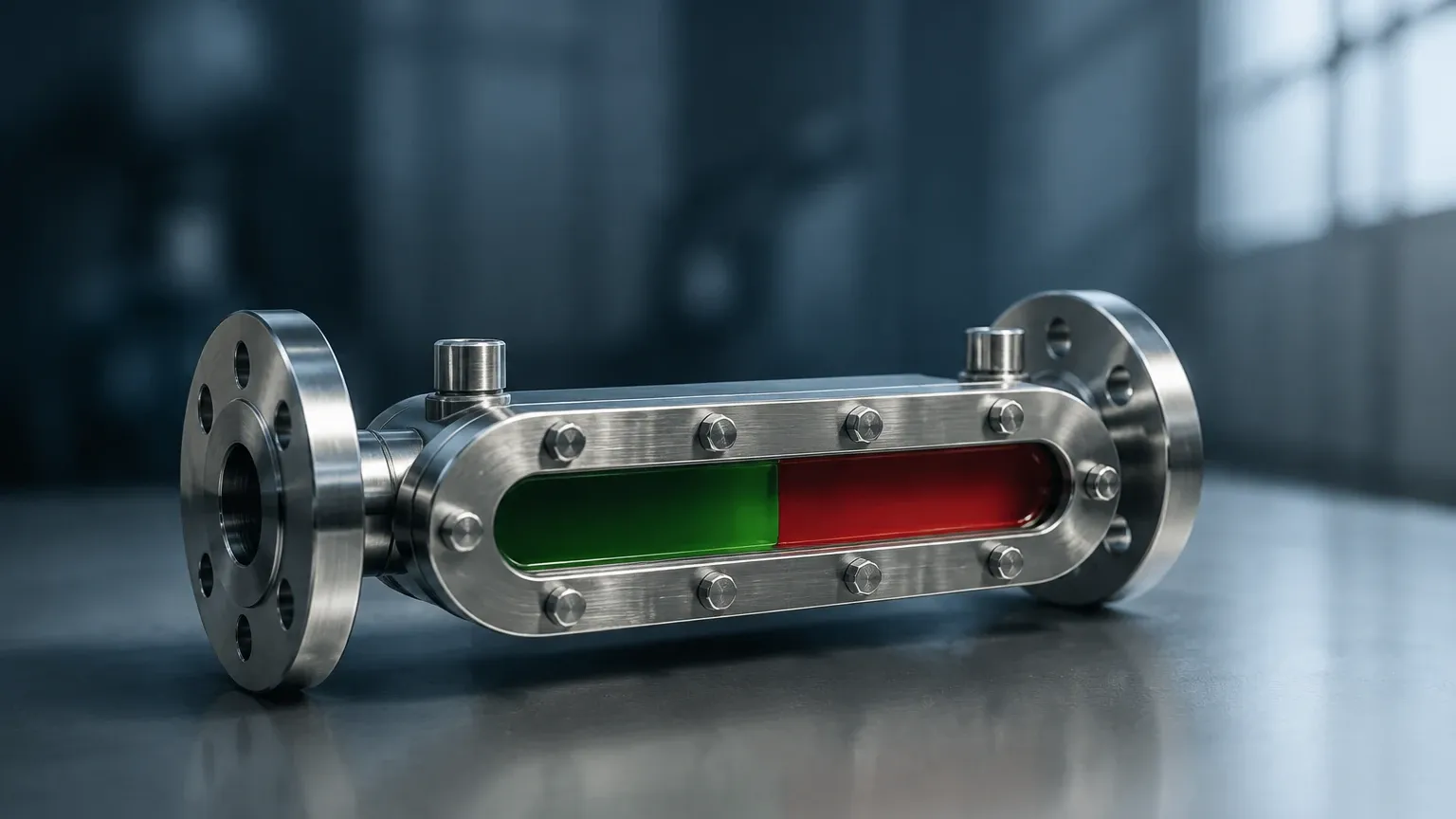
Mounted to the outside of the chamber is the indicator, which is hermetically sealed. As the liquid level rises or falls, the float moves accordingly. The magnetic field from the float passes through the chamber wall—which is made of non-magnetic material like 316 Stainless Steel or PVC—and acts upon the indicator. This indicator usually consists of a series of bi-color magnetic flags or a magnetic follower (shuttle). The flags flip 180 degrees as the float passes, changing color (typically from white to red) to provide a clear, high-visibility representation of the level.
Understanding the 3/4" Connection Standard
The term "3 4 level gauge" specifically denotes the size of the process connection that interfaces with the vessel. In the context of Welk industrial solutions, the 3/4-inch size is a standard for several reasons:
1. Mechanical Strength: A 3/4-inch (approx. 19 mm) connection provides significantly more structural integrity than a 1/2-inch connection, especially for taller gauges that may be subject to vibration or mechanical stress.
2. Flow Dynamics: The 3/4-inch bore allows for faster equalization of the liquid level between the tank and the gauge chamber, reducing lag in readings during rapid filling or emptying cycles.
3. Standardization: Most industrial piping specifications for chemical and oil and gas applications standardize on 3/4-inch or 1-inch NPT/flanged outlets for auxiliary instrumentation.
Connection Types
* NPT (National Pipe Thread): Common in North American installations for pressures up to 3000 psi, depending on the material. It offers a compact, threaded seal.
* Flanged (ANSI/ASME or DIN): Preferred in high-pressure or hazardous chemical applications where a bolted, gasketed seal is required for leak prevention and ease of maintenance.
Key Evaluation Criteria for 3/4 Level Gauges
When specifying a 3 4 level gauge, engineers must evaluate several parameters to ensure the instrument survives the process conditions and provides accurate data.
Material Compatibility
The wetted parts (chamber and float) must be chemically resistant to the process fluid. Common materials include:
* 316L Stainless Steel: The standard for water, oils, and mild chemicals.
* Hastelloy or Monel: Used for highly corrosive acids or seawater applications.
* Plastics (PP, PVDF, PVC): Ideal for low-pressure corrosive applications where metals are unsuitable.
Specific Gravity (SG)
The float must be lighter than the liquid to remain buoyant but heavy enough to stay submerged to the midpoint of the magnet assembly. If the SG of the fluid changes (e.g., due to temperature fluctuations), the accuracy of the 3 4 level gauge may be affected. Standard floats are usually designed for an SG range of 0.5 to 1.5.
Pressure and Temperature Ratings
Because the magnetic gauge is a pressure vessel, it must be rated for the Maximum Allowable Working Pressure (MAWP) of the tank. High-temperature applications (above 200°C / 392°F) require specialized insulation and high-curie-point magnets to ensure the magnetic field does not degrade.
Selection Table for Magnetic & Local Level Gauges
The following table provides a comparison of common 3/4-inch level gauge configurations used in industrial automation.
| Feature | Magnetic Level Gauge | Reflex Glass Gauge | Transparent Glass Gauge |
| :— | :— | :— | :— |
| Visibility | Excellent (up to 30m distance) | Moderate | Moderate |
| Pressure Limit | Up to 200 bar (2900 psi) | Up to 40 bar (580 psi) | Up to 100 bar (1450 psi) |
| Hazardous Fluids | Safest (No glass to break) | Risk of glass failure | Risk of glass failure |
| Interface Level | Yes (with specific float) | Difficult | Possible with backlight |
| Maintenance | Low (Internal cleaning) | High (Cleaning/Gaskets) | High (Cleaning/Gaskets) |
| Process Conn. | 3/4" NPT / Flange | 3/4" NPT / Flange | 3/4" NPT / Flange |
Installation Considerations for 3/4" Level Gauges
Proper installation is critical for the longevity and accuracy of a 3 4 level gauge. Since these are mechanical instruments, physical alignment and environmental factors play a significant role.
Orientation and Support
The gauge must be installed perfectly vertical. If the chamber is tilted by more than 2-3 degrees, the float may experience friction against the chamber walls, leading to "sticking" or inaccurate readings. For gauges exceeding 3 meters (approx. 10 feet) in length, intermediate support brackets are required to prevent the 3/4-inch connections from bearing the full weight of the instrument.
Isolation Valves and Venting
It is highly recommended to install 3/4-inch isolation valves (ball or needle valves) between the tank and the gauge. This allows the gauge to be serviced or cleaned without depressurizing the main vessel. Additionally, the gauge should feature a vent plug at the top and a drain valve at the bottom to facilitate the removal of trapped air or sediment.
Magnetic Interference
Because the measurement principle relies on magnetism, the 3 4 level gauge must be kept away from large ferrous structures or high-voltage power lines that could create electromagnetic interference. A minimum clearance of 100 mm (4 inches) from carbon steel supports is generally advised.
Limitations and Operational Risks
While Magnetic & Local Level Gauges are highly reliable, they are not universal solutions. Engineers should be aware of the following limitations:
* Particulate Matter: If the process fluid contains magnetic particles (e.g., iron filings or scale), these particles can adhere to the float’s magnet, increasing its weight and causing it to sink or jam. In such cases, a magnetic filter should be installed in the bypass line.
* High Viscosity: Extremely viscous liquids (above 500 cP) can impede the movement of the float. For these applications, larger diameter chambers or specialized float coatings may be necessary.
* Coating and Scaling: If the fluid tends to crystallize or leave heavy deposits, the float may become stuck. Regular flushing via the drain connection is required in these environments.
* Flash Vaporization: Rapid boiling or flashing within the chamber can cause the float to bounce violently, potentially damaging the internal stops or the magnet assembly.
Frequently Asked Questions (FAQ)
Can a 3 4 level gauge be used for steam applications?
Yes, but specialized designs are required. For high-pressure steam, magnetic level gauges are often preferred over glass because they eliminate the risk of "thinning" or etching of the glass by the alkaline steam condensate. Ensure the gauge is rated for the specific saturated steam pressure.
How do I calibrate a magnetic 3/4-inch level gauge?
Magnetic gauges are technically "self-calibrating" because the float naturally follows the liquid level. However, the external indicator scale must be aligned correctly during commissioning. If a transmitter (such as a reed chain or magnetostrictive sensor) is added to the gauge for remote monitoring, that component will require standard 4-20mA or HART calibration.
What is the difference between a 3/4" NPT and a 3/4" Flange connection for these gauges?
3/4" NPT is a threaded connection that is easier to install in tight spaces but is generally limited to lower pressure classes or non-hazardous fluids. A 3/4" flange (e.g., ANSI 150# or 300#) provides a more robust, leak-proof seal and is the standard for chemical plants where safety regulations mandate flanged connections for all process penetrations.
Can I use a 3 4 level gauge for measuring the interface between two liquids?
Yes. By weighting the float to a density between the specific gravities of the two liquids (e.g., water and oil), the float will sink through the upper layer and float on the lower layer, providing a clear indication of the interface level.
Conclusion
The 3 4 level gauge remains a cornerstone of local level indication due to its standardized sizing and mechanical reliability. Whether utilizing a magnetic system for hazardous chemicals or a local glass gauge for utility water, selecting the right instrument involves a careful balance of pressure ratings, material science, and installation best practices. For complex applications, consulting with a manufacturer like Welk ensures that the float design and chamber materials are optimized for the specific gravity and chemical profile of your process, resulting in a long-lasting and maintenance-free measurement solution.