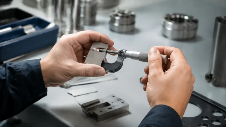
U Level Calibration
U Level Calibration
In the landscape of industrial process control, the accuracy of level measurement is a fundamental requirement for both operational efficiency and plant safety. Among the various technologies available, local level indicators provide a critical visual reference for operators on the plant floor. However, ensuring that these instruments reflect the true liquid level within a vessel requires a rigorous approach to calibration. This guide explores the principles of u level calibration specifically within the context of Magnetic & Local Level Gauges, offering engineering insights into their operation, selection, and maintenance.
Understanding the Principles of Local Level Measurement
Before addressing the specifics of calibration, it is essential to understand the mechanical and physical principles that govern local level indicators. Most industrial applications rely on two primary types of local gauges: the traditional glass level gauge and the modern magnetic level gauge (MLG).
The Buoyancy Principle
Magnetic level gauges operate on the principle of buoyancy (Archimedes' Principle) and magnetic coupling. The system consists of a bypass chamber—essentially a vertical pipe mounted to the side of the vessel—and a float containing an internal magnet assembly. As the liquid level in the vessel rises or falls, the liquid level in the bypass chamber follows suit due to the law of communicating vessels (the "U-tube" effect).
The float, engineered to match the specific gravity of the process fluid, moves with the liquid level. Its internal magnets actuate a series of bi-color magnetic flags or rollers located in an external indicator scale. This provides a clear, high-visibility representation of the level without the process fluid ever coming into contact with the viewing glass, significantly reducing the risk of leaks or glass breakage.
The Hydrostatic "U" Relationship
The term "u level calibration" often refers to the verification of the hydrostatic balance between the vessel and the external gauge. In a perfectly balanced system, the liquid level in the bypass chamber should be identical to the level in the main vessel. However, factors such as temperature gradients, fluid density variations, and pressure differentials can create a "U-shaped" discrepancy where the levels do not match perfectly. Calibration is the process of identifying and correcting these offsets to ensure the indicated level is the true level.
The Importance of U Level Calibration
Calibration is not merely a setup task but a continuous requirement for high-accuracy environments. In many chemical and oil and gas applications, a discrepancy of even a few millimeters can lead to inventory errors or, in worse cases, the failure of a high-level alarm system.
Magnetic & Local Level Gauges are often used as the primary redundant check for electronic transmitters. If the local gauge is not calibrated correctly, the operator may receive conflicting information, leading to hesitation during critical process shifts. The "u level" verification ensures that the physical position of the float corresponds exactly to the scale markings on the indicator.
Practical Calibration Procedures for Magnetic Gauges
Calibrating a magnetic level gauge involves verifying the zero point, the span, and the alignment of any attached transmitters or switches. Unlike electronic sensors that can be calibrated via software, MLGs require a combination of physical and mechanical adjustments.
1. Pre-Calibration Requirements
Before starting the calibration, ensure the following conditions are met:
* Fluid Density Verification: Confirm the process fluid density matches the float's design specifications. If the density has changed (e.g., due to a change in chemical composition), the float will sit higher or lower in the liquid, requiring a scale offset.
* Vertical Alignment: Use a spirit level to ensure the bypass chamber is perfectly vertical. An inclination of even 1-2 degrees can cause float friction, leading to "sticking" and inaccurate readings.
* Isolation: Ensure the gauge is properly isolated from the process if a wet calibration is being performed using a secondary fluid.
2. Zero-Point Calibration (U-Level Alignment)
The zero point is the most critical aspect of u level calibration. It represents the lowest measurable point, typically corresponding to the center of the bottom process connection.
* Manual Zeroing: For magnetic flags, a small external magnet is used to "flip" all flags to the "empty" color (usually white or silver) below the zero line.
* Float Positioning: With the chamber empty, the float should rest at the bottom spring. The indicator scale must be adjusted so that the "zero" mark aligns with the magnetic center of the float in this resting position.
3. Span and Linearity Check
To verify the span, the level must be raised to the maximum operating point. This can be done by filling the vessel or by using a calibration tube if the gauge is isolated.
* Comparison: Compare the indicator reading against a known reference, such as a dip tape measurement or a calibrated radar level meter.
* Adjustment: If the gauge reads 500 mm when the actual level is 510 mm, the scale or the magnetic flags must be shifted to compensate for the offset.
4. Synchronizing External Transmitters
Many MLGs are equipped with reed-chain or magnetostrictive transmitters. Once the physical scale is calibrated, the electronic output (4-20mA or HART) must be mapped to the physical 0% and 100% points. This ensures that the control room sees exactly what the operator sees on the local scale.
Selection Table: Comparing Local Level Technologies
Choosing the right instrument is the first step toward easier calibration. The following table compares common local indicators used in industrial automation.
| Feature | Magnetic Level Gauge (MLG) | Glass Level Gauge | Ultrasonic Level Sensor (Local Display) |
| :— | :— | :— | :— |
| Visibility | High (Bi-color flags) | Moderate (Visual liquid) | Digital Display Only |
| Pressure Rating | Up to 400 bar (5800 psi) | Limited by glass strength | Non-contact (N/A) |
| Maintenance | Low (No glass to clean) | High (Staining/Leaking) | Low (Electronic) |
| Calibration Complexity | Moderate (Mechanical/Float) | Low (Visual) | High (Software/Echo) |
| Safety | High (Total Containment) | Moderate (Risk of breakage) | High |
| U Level Accuracy | Excellent (Density dependent) | Direct (Density independent) | Electronic (Density independent) |

Installation Considerations for Accuracy
To maintain the integrity of u level calibration over time, the installation must follow strict engineering guidelines:
1. Avoid Magnetic Interference: Keep the gauge at least 100 mm (4 inches) away from large carbon steel structures, motors, or high-voltage cables. Magnetic fields can interfere with the float's movement or cause the flags to flip prematurely.
2. Thermal Insulation: In high-temperature applications, the bypass chamber should be insulated. Temperature gradients between the vessel and the chamber can cause density differences (the "U-tube" error), leading to a level discrepancy where the gauge reads lower than the vessel.
3. Venting and Draining: Always install a vent valve at the top and a drain valve at the bottom of the chamber. This allows for easy cleaning of debris that might impede float movement and facilitates field calibration without decommissioning the entire vessel.
Common Risks and Limitations
While Magnetic & Local Level Gauges are robust, they are not without limitations. Engineers should be aware of the following risks during the calibration and operation phases:
* Coating and Buildup: In viscous or crystallizing fluids, material can build up on the float or the internal walls of the chamber. This increases the weight of the float or causes it to stick, rendering the u level calibration invalid. Regular flushing is required.
* Flash Evaporation: If the process fluid is near its boiling point, a pressure drop in the bypass chamber can cause the liquid to flash into gas. This creates bubbles that lift the float artificially high.
* Extreme Density Changes: If a plant switches from a fluid with a specific gravity of 0.8 to one with 1.2, the original float will no longer be accurate. A new float must be engineered and the scale recalibrated.
Frequently Asked Questions (FAQs)
Q: How often should I perform a u level calibration on my magnetic gauge?
A: For most stable processes, an annual verification is sufficient. However, in high-vibration environments or processes with heavy scaling, semi-annual checks are recommended.
Q: Can I calibrate a magnetic level gauge while the tank is in operation?
A: Yes, if the gauge is equipped with isolation valves. You can close the valves, drain the chamber, and use a reference fluid or a mechanical calibration tool to verify the float and indicator response.
Q: Why does my local gauge show a different level than my radar transmitter?
A: This is often due to density differences. Radar measures the distance to the surface regardless of density, whereas a magnetic gauge depends on buoyancy. If the fluid density is lower than the design spec, the float will sink deeper, showing a lower level than the radar.
Q: Is it possible to use one float for multiple liquids?
A: Only if the densities are very similar (within +/- 0.05 SG). Otherwise, the buoyancy offset will exceed acceptable calibration tolerances.
Conclusion
Effective u level calibration is the cornerstone of reliable local level monitoring. By understanding the hydrostatic relationship between the vessel and the gauge, and by following systematic calibration procedures, plant engineers can ensure that their Magnetic & Local Level Gauges provide the accuracy required for modern industrial standards. Whether you are managing water treatment facilities or complex chemical reactors, prioritizing the mechanical alignment and density-specific calibration of your local indicators is essential for long-term operational success.