Visual Level Gauge
Visual Level Gauge
In industrial process control, the ability to verify tank levels through direct observation remains a critical safety and operational requirement. While electronic sensors provide data to centralized control systems, a visual level gauge serves as the primary local reference point for operators on the plant floor. These instruments provide a fail-safe, mechanical indication of liquid levels that does not rely on power, making them indispensable in hazardous environments, power generation, and chemical processing.
At its core, a visual level gauge operates on the principle of communicating vessels, where the liquid level in a bypass chamber or glass tube matches the level within the main process vessel. This article explores the engineering principles, selection criteria, and installation requirements for these essential instruments, with a focus on modern Magnetic & Local Level Gauges as a robust alternative to traditional glass-based indicators.
Understanding the Principles of Visual Level Measurement
The fundamental physics behind a visual level gauge is Pascal’s Law and the principle of communicating vessels. When two or more containers are connected, a liquid will seek the same level in all containers regardless of their shape or volume, provided the pressure above the liquid remains constant across all points.
Direct vs. Indirect Visual Indication
Visual level measurement is generally categorized into two methodologies:
1. Direct Visual Indication: This involves the use of transparent tubes (sight glasses) or chambers with armored glass windows. The operator views the actual process fluid through the glass. In reflex gauges, light refraction is used to create a sharp contrast between the liquid and gas phases. In transparent gauges, light is transmitted through the fluid from the back, allowing for the observation of color, clarity, or interface layers between two immiscible liquids.
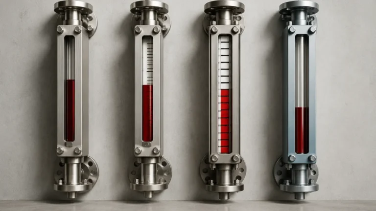
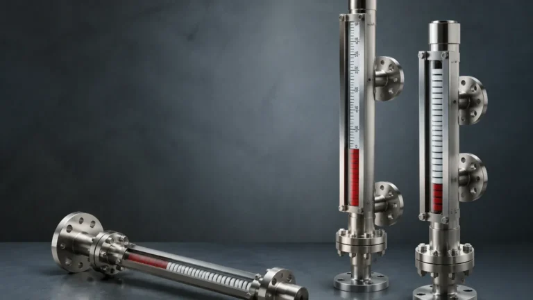
2. Indirect Visual Indication: This is the principle used by magnetic level gauges. A float containing a high-intensity permanent magnet is placed inside a non-magnetic chamber (usually stainless steel). As the liquid level rises and falls, the float moves accordingly. Outside the chamber, a visual indicator—typically consisting of bi-color magnetic rollers or flappers—responds to the magnetic field of the float. The rollers flip to show a different color (usually red for liquid and white for gas), providing a clear visual representation without the liquid ever coming into contact with the viewing glass.
Primary Types of Visual Level Gauges
Selecting the right visual level gauge requires an understanding of the specific strengths and limitations of each design.
1. Magnetic Level Gauges (MLG)
MLGs are the preferred choice for high-pressure, high-temperature, or toxic applications. Because the liquid is entirely contained within a metallic pressure chamber, the risk of glass breakage and subsequent leakage is eliminated. These gauges are highly versatile and can be equipped with reed switches or transmitters to provide both local visual indication and remote electronic signals.
2. Reflex Level Gauges
Reflex gauges feature a single glass window with a grooved inner surface. These grooves utilize the principle of total internal reflection. In the gas space, light is reflected back to the observer, appearing bright or silvery. In the liquid space, light is absorbed, making the liquid appear dark. This high contrast makes them excellent for clear liquids like water or steam condensate.
3. Transparent Level Gauges
Transparent gauges consist of two pieces of flat glass on opposite sides of the chamber. This allows light to pass through the medium. They are essential for applications where the operator needs to observe the color of the liquid, identify fouling, or monitor the interface between two different liquids (e.g., oil and water).
4. Tubular Level Gauges
The simplest form of visual level gauge, the tubular design, uses a clear plastic or glass tube connected to the tank. While cost-effective, they are generally limited to low-pressure, non-hazardous applications due to the vulnerability of the exposed tube.
Technical Selection Criteria for Industrial Projects
When specifying a visual level gauge, engineers must evaluate several parameters to ensure safety and accuracy. The following table provides a comparison of key selection factors:
| Feature | Reflex Glass Gauge | Transparent Glass Gauge | Magnetic Level Gauge |
| :— | :— | :— | :— |
| Max Pressure | Up to 4.0 MPa (40 bar) | Up to 3.2 MPa (32 bar) | Up to 42.0 MPa (420 bar) |
| Max Temperature | 400°C (with mica) | 400°C (with mica) | 530°C |
| Visibility | High (High Contrast) | Moderate | Excellent (Bi-color) |
| Interface Detection | Not Recommended | Excellent | Possible (Specific Float) |
| Hazardous Media | Low Suitability | Moderate Suitability | High Suitability |
| Maintenance | High (Glass Cleaning) | High (Glass Cleaning) | Low (Self-contained) |
Material Compatibility
The wetted materials must be compatible with the process fluid. Common materials include:
* Stainless Steel (304/316L): Standard for water, oil, and mild chemicals.
* Special Alloys (Hastelloy, Monel): For highly corrosive environments.
* Plastics (PP, PVDF, PTFE Lining): Used for aggressive acids and bases where metallic contact must be avoided.
Specific Gravity (SG)
For magnetic level gauges, the specific gravity of the fluid is the most critical design factor. The float must be engineered with a buoyancy that allows it to sit precisely at the liquid-gas interface. If the SG changes significantly due to temperature fluctuations, the float may sink or ride too high, leading to measurement errors.
Installation and Commissioning Best Practices
Proper installation is vital for the reliable performance of a visual level gauge. Failure to follow engineering standards can lead to mechanical stress, leaks, or inaccurate readings.
1. Vertical Alignment: The gauge must be installed perfectly vertical. For magnetic gauges, even a slight tilt can cause the float to frictionally bind against the chamber wall, preventing movement.
2. Valve Configuration: Every gauge should be installed with isolation valves (top and bottom). These valves often include a "ball check" safety feature that automatically shuts off flow if the glass or chamber is breached. Drain and vent valves are also necessary for commissioning and maintenance.
3. Support Brackets: For gauges exceeding 3 meters (3000 mm) in length, intermediate support brackets must be used to secure the instrument to the vessel or a support structure. This prevents vibration and mechanical fatigue on the process connections.
4. Thermal Insulation: In high-temperature or cryogenic applications, the gauge chamber should be insulated. However, the visual indicator (the rollers) on a magnetic gauge should remain outside the insulation to ensure visibility and prevent the magnets from exceeding their Curie temperature (the point where they lose magnetic properties).

Maintenance, Troubleshooting, and Limitations
While visual level gauges are mechanically simple, they are not maintenance-free.
Common Maintenance Tasks
* Cleaning: Glass gauges require periodic cleaning of the internal and external glass surfaces to maintain visibility. Magnetic gauges may require flushing the chamber if the process fluid contains solids or magnetic particles (fines) that could stick to the float.
* Seal Inspection: Gaskets and O-rings should be inspected for signs of degradation, especially in high-pressure steam applications where "thinning" of the glass can occur over time.
Limitations to Consider
* Fouling and Scaling: If the process fluid is prone to heavy scaling or crystallization, the narrow passages of a visual gauge can become blocked. In such cases, large-bore chambers or specialized coatings may be required.
* Magnetic Interference: Magnetic level gauges should not be installed near high-power electric motors or large ferrous structures that could distort the magnetic field and affect float movement.
* Density Sensitivity: Since these are buoyancy-based instruments, they are sensitive to changes in fluid density. If a tank is used for multiple different fluids, the gauge may need to be recalibrated or the float replaced.
Frequently Asked Questions (FAQ)
Q: Can a visual level gauge be used for underground tanks?
A: Standard bypass visual gauges require side-mounting, which is impractical for underground tanks. However, top-mounted magnetic level gauges with a float-and-rod assembly can be used to provide a local visual reading at ground level.
Q: What is the maximum length for a single visual level gauge?
A: While individual glass sections are usually limited to about 300-500 mm to prevent breakage, multiple sections can be joined to cover several meters. Magnetic level gauges can be manufactured in single lengths up to 6 meters, or even longer using sectional designs.
Q: How do I handle fluids that tend to coat the glass?
A: For glass gauges, a transparent design with a protective mica shield or a specific chemical coating can help. However, the most effective solution for coating fluids is often switching to a magnetic level gauge, as the visual indicator is completely isolated from the fluid.
Q: Are visual level gauges suitable for high-vibration environments?
A: Traditional glass gauges are susceptible to cracking under high vibration. Magnetic level gauges are much more robust, though the visual flappers should be checked to ensure they are dampened or secured against accidental flipping.
Conclusion
The visual level gauge remains a cornerstone of industrial safety and process monitoring. Whether utilizing the direct clarity of a reflex glass or the advanced safety features of Magnetic & Local Level Gauges, these instruments provide the essential "ground truth" that operators need to manage complex systems. By carefully considering fluid properties, pressure requirements, and installation geometry, engineers can implement a level measurement solution that offers both long-term reliability and ease of use.