Gauge Locations
Gauge Locations
In industrial process control, the physical placement of level measurement instruments is as critical as the technology itself. For engineers and plant operators, determining the optimal gauge locations ensures not only the accuracy of the data collected but also the safety of the personnel and the longevity of the equipment. Local level indicators, particularly Magnetic & Local Level Gauges, serve as the primary visual reference on-site, providing a fail-safe verification of the liquid level that is independent of the plant’s electrical power supply.
Selecting the correct position for these instruments requires a comprehensive understanding of vessel geometry, fluid dynamics, and maintenance accessibility. This guide explores the technical principles of local level gauges and provides a framework for evaluating the best installation points within a process facility.
Measurement Principles of Magnetic Level Gauges
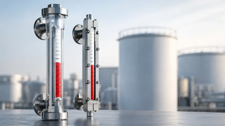
Before determining specific gauge locations, it is essential to understand how these instruments function. A magnetic level gauge operates on the principle of buoyancy and magnetic coupling. The system consists of three primary components:
1. The Chamber: A vertical column, typically constructed from non-magnetic stainless steel or engineered plastics, connected to the process vessel via nozzles.
2. The Float: A sealed, pressurized float containing an internal permanent magnet. The float is engineered to have a specific gravity lower than the process liquid, allowing it to ride accurately on the liquid surface.
3. The Indicator: An external scale or a series of magnetic flags (flappers) mounted to the outside of the chamber.
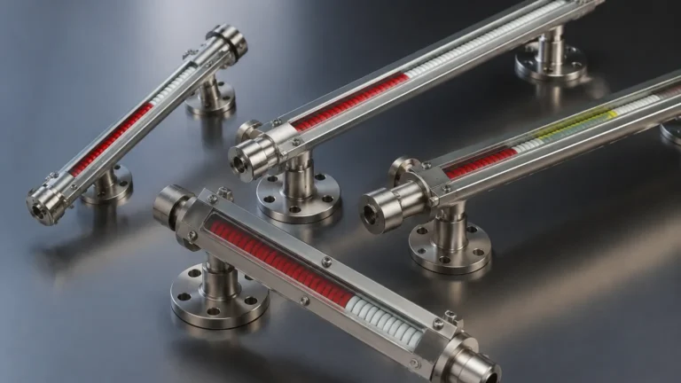
As the liquid level in the vessel rises or falls, the float inside the chamber moves accordingly. The magnetic field from the float penetrates the chamber wall and interacts with the external indicator. In a flag-style indicator, the magnetic force flips the flags to a different color (usually red for liquid and white for gas/vapor), creating a high-visibility representation of the level. Because the indicator is completely isolated from the process fluid, there is no risk of leaks or glass breakage, which is a common limitation of traditional sight glasses.
Key Criteria for Determining Gauge Locations
When planning the layout of a vessel or piping system, the following factors must be evaluated to identify the most effective gauge locations.
1. Visibility and Line of Sight
Local gauges are intended for human observation. Therefore, the primary location requirement is that the indicator must be visible from primary walkways, platforms, or control stations. Engineers should consider the height of the gauge relative to the operator's eye level. If a gauge must be located high on a tall column, the indicator should be oversized or angled to allow for reading from the ground level.
2. Process Connection Alignment
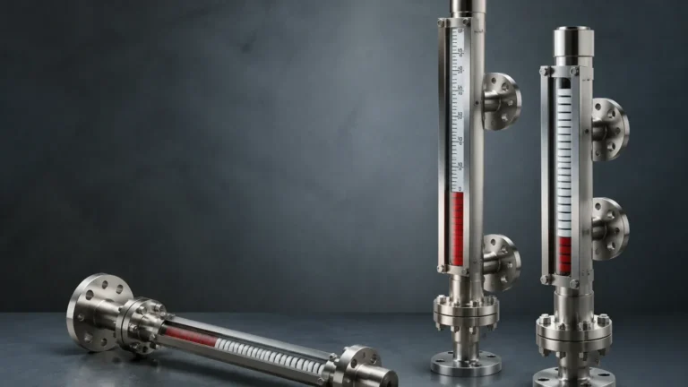
The nozzles on the vessel dictate the height and range of the measurement. For a side-side configuration, the "center-to-center" distance between the top and bottom process connections defines the visible range. It is vital to ensure that the gauge locations align with the operating range of the vessel—specifically the high-level and low-level alarm points. If the nozzles are placed too close together, the gauge may not capture critical overflow or dry-run conditions.
3. Turbulence and Fluid Entry Points
Gauge locations should be away from high-velocity inlet streams, agitators, or areas of extreme turbulence. If a gauge is placed directly opposite an inlet pipe, the incoming fluid can cause the float to bounce or vibrate excessively, leading to premature wear of the float or inaccurate readings. In vessels with high agitation, a stilling well or a diverted bypass configuration is often necessary to provide a stable liquid surface for the float.
4. Structural Clearance and Maintenance Access
Magnetic level gauges require periodic inspection and, occasionally, float removal for cleaning. When selecting gauge locations, ensure there is sufficient overhead or bottom clearance to extract the float from the chamber. For a 2-meter (approx. 6.5 ft) gauge, you typically need at least 0.5 meters (500mm) of clearance at the bottom or top, depending on the flange design, to facilitate maintenance without dismantling the entire piping assembly.
Comparison of Common Mounting Configurations
The choice of mounting configuration significantly influences the final gauge locations on a tank or reactor. The following table outlines the standard options used in industrial applications.
| Mounting Type | Typical Application | Advantages | Limitations |
| :— | :— | :— | :— |
| Side-Side | Storage tanks, bypass chambers | Easiest to install and maintain; clear visibility. | Requires two vessel penetrations. |
| Top-Mounted | Underground tanks, sumps | No side penetrations needed; ideal for hazardous fluids. | Limited by float rod length; requires vertical clearance above the tank. |
| Side-Bottom | Horizontal drums, boilers | Captures the very bottom of the vessel level. | Can be prone to sediment buildup in the bottom connection. |
| Top-Side | Small vessels with limited space | Minimizes footprint while maintaining side visibility. | Complex internal float dynamics. |
Installation Considerations and Best Practices
Once the general gauge locations are identified, technical installation details must be addressed to ensure reliable performance.
Avoiding Magnetic Interference
Since the instrument relies on magnetic coupling, it must be located away from large ferrous structures or high-voltage electrical equipment. Proximity to heavy steel beams or large motors can distort the magnetic field, causing the float to stick or the indicator to provide false readings. A minimum clearance of 100mm to 150mm from carbon steel structures is generally recommended.
Thermal Insulation and Heat Tracing
In applications involving high-temperature fluids or cryogenic liquids, the gauge location must account for thermal expansion and the need for insulation. If the process fluid is prone to solidification (like bitumen or heavy wax), the gauge chamber may require steam jackets or electric heat tracing. When planning these gauge locations, ensure that the insulation does not obscure the visual indicator.
Venting and Draining
Every local level gauge installation should include a vent valve at the highest point and a drain valve at the lowest point. These are essential for commissioning and for safely depressurizing the chamber during maintenance. The location of these valves must be accessible to operators and should ideally be piped to a safe recovery system or floor drain.

Limitations and Risks of Improper Placement
Choosing incorrect gauge locations can lead to several operational risks:
* Dead Zones: If the bottom nozzle is placed too high, the gauge will show an "empty" reading even when a significant volume of liquid remains in the tank. This is known as the "dead zone" below the bottom process connection.
* Float Damage: Placing a gauge in a location subject to water hammer or rapid pressure surges can collapse the float, rendering the gauge useless.
* Coating and Scaling: In applications with dirty fluids, placing the gauge in a stagnant area of the vessel may encourage the buildup of scale or debris inside the chamber, eventually pinning the float in place.
Frequently Asked Questions (FAQs)
Q: Can I install a magnetic level gauge horizontally?
A: No. These instruments rely on gravity and buoyancy to move the float within the chamber. They must be installed vertically within a tolerance of usually +/- 3 degrees to ensure the float moves freely.
Q: What is the maximum distance a gauge can be from the vessel?
A: While there is no strict maximum distance, the piping between the vessel and the gauge should be as short and direct as possible to ensure the level in the gauge accurately reflects the level in the vessel. Long horizontal runs can lead to temperature differences and density variations, causing measurement errors.
Q: How do I handle gauge locations for very tall tanks?
A: For tanks exceeding 5 or 6 meters, a single continuous chamber may be difficult to ship and install. In these cases, multiple gauges can be staggered (overlapped) to cover the full height, or the chamber can be manufactured in sections with flanged joints.
Q: Are there specific requirements for gauge locations in seismic zones?
A: Yes. In areas prone to vibration or seismic activity, the gauge chamber must be supported by additional brackets attached to the vessel or surrounding structure to prevent mechanical fatigue at the nozzle welds.
Conclusion
Selecting appropriate gauge locations is a fundamental step in process plant design. By prioritizing visibility, accessibility, and the physical characteristics of the process fluid, engineers can ensure that Magnetic & Local Level Gauges provide reliable service for years. Whether dealing with high-pressure steam or corrosive chemicals, the correct placement of these instruments remains a cornerstone of effective local level monitoring and overall site safety. Before finalizing a design, always verify that the chosen locations provide sufficient clearance for maintenance and are free from magnetic or mechanical interference.