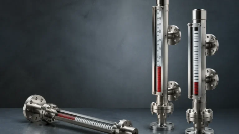
1 Level Gauge
1 Level Gauge
In industrial process control, the term "1 level gauge" often refers to the primary, standalone instrument used for local visual verification of liquid levels within a tank or pressure vessel. While modern plants rely heavily on automated sensors and remote monitoring systems, the local level gauge remains an indispensable safety and operational tool. It provides a direct, mechanical readout that functions independently of power supplies, control loops, or software algorithms. This article explores the engineering principles, selection criteria, and technical applications of these essential instruments, focusing on the transition from traditional sight glasses to advanced magnetic technologies.
The Role of Local Level Indication
A local level gauge serves as the "ground truth" for plant operators. Even in highly automated environments, a manual check of the vessel level is required during commissioning, maintenance, and emergency shutdowns. The primary requirement for a 1 level gauge is reliability; it must provide an accurate representation of the liquid level under varying temperatures and pressures without the risk of electronic failure.
Historically, direct-reading glass gauges were the standard. However, due to the inherent risks of glass breakage and leakage—especially when handling hazardous or high-pressure media—the industry has shifted toward Magnetic & Local Level Gauges. These instruments use magnetic coupling to isolate the process fluid from the indicator, significantly enhancing safety while maintaining a clear visual interface.
Measurement Principles
Understanding how a level gauge functions is critical for selecting the correct model for a specific application. Most local gauges operate on one of three fundamental principles: buoyancy, hydrostatic pressure, or direct visual refraction.
1. The Buoyancy Principle (Magnetic Level Gauges)
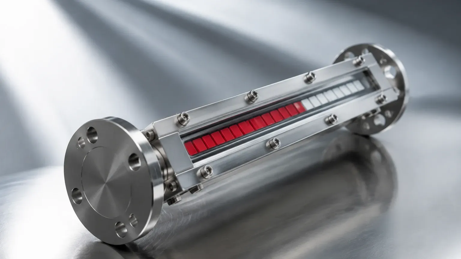
Magnetic level gauges operate based on Archimedes' principle. A float is designed with a specific buoyancy to match the density of the process liquid. Inside this float is a permanent magnet assembly. The float resides within a non-magnetic bypass chamber (usually stainless steel) connected to the side of the vessel.
As the liquid level rises and falls, the float moves accordingly. Outside the chamber, a visual indicator—typically a series of bi-color magnetic flags or a magnetic follower—is coupled to the float's internal magnet. When the float passes, the magnetic field flips the flags (e.g., from white to red) or moves the follower, providing a clear, high-visibility indication of the level. This method ensures that the process fluid is entirely contained within the pressure-sealed chamber.
2. Direct Visual Refraction (Glass Gauges)
Direct-reading gauges use a transparent or reflex glass window bolted to a metal body. In a reflex gauge, the inner surface of the glass has prismatic grooves. The difference in the refractive index between the liquid and the gas (vapor) causes light to be absorbed or reflected. Typically, the liquid column appears dark, while the gas space appears bright, creating a sharp line of demarcation.
3. Hydrostatic Pressure
While less common for purely visual "gauges," some local indicators use a bellows or diaphragm system to sense the head pressure of the liquid column. This pressure is then mechanically converted into a dial reading. This is often used in vented tanks where a top-mounted or side-mounted dial is more practical than a vertical column.
Technical Comparison and Selection
Choosing the right 1 level gauge requires a comparison of technologies based on the process environment. The following table outlines the primary differences between common local level indication methods.
| Feature | Magnetic Level Gauge | Reflex Glass Gauge | Transparent Glass Gauge |
| :— | :— | :— | :— |
| Visibility | High (Flags/Follower) | Moderate (Prismatic) | Low (Needs Illumination) |
| Pressure Range | Up to 400 bar (5800 psi) | Up to 250 bar (3625 psi) | Up to 340 bar (4930 psi) |
| Temperature Range | -196°C to 450°C | Up to 400°C | Up to 400°C |
| Safety | Excellent (No glass) | Fair (Risk of breakage) | Fair (Risk of breakage) |
| Maintenance | Low | High (Cleaning/Gaskets) | High (Cleaning/Gaskets) |
| Media Type | Corrosive, Toxic, Dirty | Clean, Non-corrosive | Interface, Dirty, Steam |
Key Evaluation Criteria for Industrial Applications
When specifying a 1 level gauge for a project, engineers must confirm several technical parameters to ensure long-term performance and safety.
Media Density and Specific Gravity
For magnetic gauges, the float must be custom-engineered to the specific gravity (SG) of the fluid. If the SG is too low (e.g., liquefied gases at < 0.5 SG), the float may need to be larger or made of specialized materials like titanium to ensure it remains buoyant. If the fluid density changes significantly due to temperature fluctuations, the gauge reading may experience a slight offset.
Pressure and Temperature Ratings
The gauge body and connections must meet the vessel's design pressure. In high-temperature applications (above 250°C / 482°F), specialized magnetic materials (such as Alnico or Samarium Cobalt) are required to prevent the magnets from losing their field strength (demagnetization).
Material Compatibility
The wetted parts—the chamber, float, and gaskets—must be compatible with the process media. Common materials include:
* 304/316L Stainless Steel: Standard for water, oil, and mild chemicals.
* Hastelloy/Monel: For highly corrosive acids or seawater.
* Plastic (PP/PVDF/PVC): For low-pressure corrosive chemical storage.
* PTFE Lining: Used for aggressive chemicals where metal contact is prohibited.
Installation Considerations
Proper installation is paramount for the accuracy of a 1 level gauge. Because these instruments rely on the law of communicating vessels, the piping and orientation must allow for free fluid movement.
1. Vertical Alignment: The gauge must be installed perfectly vertical. Even a slight tilt can cause the float in a magnetic gauge to rub against the chamber walls, leading to friction and inaccurate readings.
2. Isolation Valves: Always install isolation valves (ball or needle valves) between the vessel and the gauge. This allows for maintenance or replacement without depressurizing the entire system.
3. Vent and Drain: A vent valve at the top and a drain valve at the bottom of the gauge chamber are essential for flushing out sediment and safely emptying the gauge during shutdowns.
4. Bypass Chamber Diameter: Ensure the bypass pipe diameter (typically DN50 or 2 inches) is sufficient for the float to move freely, especially if the fluid has a high viscosity.
Limitations and Risks
While highly reliable, local level gauges have specific limitations that must be addressed during the design phase:
* Magnetic Particles: In systems with significant iron filings or magnetic scale (common in old piping), particles can attach to the float magnet, causing it to stick or become too heavy to float. Magnetic filters or traps should be installed in the bypass line in such cases.
* Viscosity: Extremely viscous fluids (above 500 cP) can slow the response time of the float or cause it to stick. Heating jackets (steam or electric) are often used to maintain fluid fluidity within the gauge chamber.
* Coating and Scaling: If the process media tends to crystallize or leave heavy deposits, the internal chamber may require regular flushing to prevent the float from seizing.
Integration with Automation
A 1 level gauge is often the foundation for more complex monitoring. By adding external sensors to a magnetic level gauge, it can serve dual purposes:
* Reed Switches: These can be clamped to the outside of the chamber to provide high or low-level alarms.
* Magnetostrictive Transmitters: These sensors provide a continuous 4-20mA or HART signal to the control room by sensing the position of the float's magnet through the chamber wall. This provides a redundant electronic reading that matches the local visual reading exactly.
Frequently Asked Questions (FAQ)
Q: Can a magnetic level gauge be used for interface measurement between two liquids?
A: Yes. By weighting the float to sink in the upper (lighter) liquid but float on the lower (heavier) liquid, the gauge will accurately indicate the interface level. A minimum density difference of 0.1 g/cm³ is typically required.
Q: How often should a local level gauge be calibrated?
A: Mechanical gauges like magnetic or glass types do not require "calibration" in the electronic sense. However, they should be inspected annually for float integrity, chamber cleanliness, and gasket leaks.
Q: What happens if the float in a magnetic gauge is crushed by overpressure?
A: If the pressure exceeds the float's collapse rating, the float will sink, and the visual indicator will drop to the bottom (zero). It is vital to specify a float rating that exceeds the maximum possible surge pressure of the system.
Q: Are these gauges suitable for sanitary applications in the food industry?
A: Yes, provided they are manufactured with tri-clamp fittings and polished stainless steel (Ra < 0.8μm) to prevent bacterial growth and allow for CIP (Clean-In-Place) procedures.
By following these engineering guidelines and selecting high-quality Magnetic & Local Level Gauges, industrial facilities can ensure a reliable, maintenance-friendly solution for their primary level indication needs.