10 Level Gauge
10 Level Gauge
In industrial process control, the requirement for reliable, real-time visual verification of liquid levels remains a cornerstone of safety and operational efficiency. While electronic sensors provide the data necessary for automation, local level indicators offer a fail-safe manual reference. The term 10 level gauge often refers to high-capacity magnetic level indicators designed for significant measuring ranges—typically reaching up to 10 meters (10,000 mm) or more—which are essential for large-scale storage tanks and processing vessels.
This guide explores the technical foundations, selection criteria, and installation best practices for Magnetic & Local Level Gauges, focusing on how these instruments provide clear visibility and high-pressure performance in demanding B2B environments.
Measurement Principles of Magnetic Level Gauges
Understanding the physics behind a 10 level gauge is essential for correct application. Most modern local gauges utilize the principle of magnetic coupling combined with buoyancy.
The Principle of Communicating Vessels
A magnetic level gauge is typically mounted to the side of a vessel via two nozzles (process connections). According to the law of communicating vessels, the liquid level inside the gauge chamber will always equalize with the liquid level inside the main tank. This ensures that the instrument provides a real-time, accurate representation of the vessel's contents.
Magnetic Coupling and Buoyancy
Inside the chamber, a specially engineered float is designed to match the specific gravity (density) of the process fluid. This float contains a high-intensity permanent magnet. As the liquid level rises or falls, the float moves accordingly.
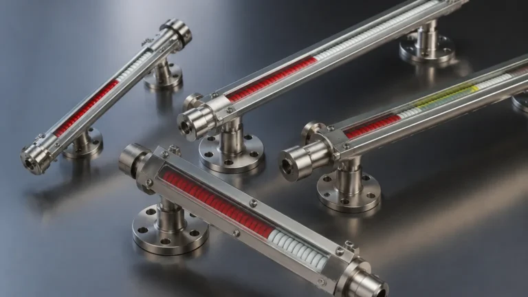
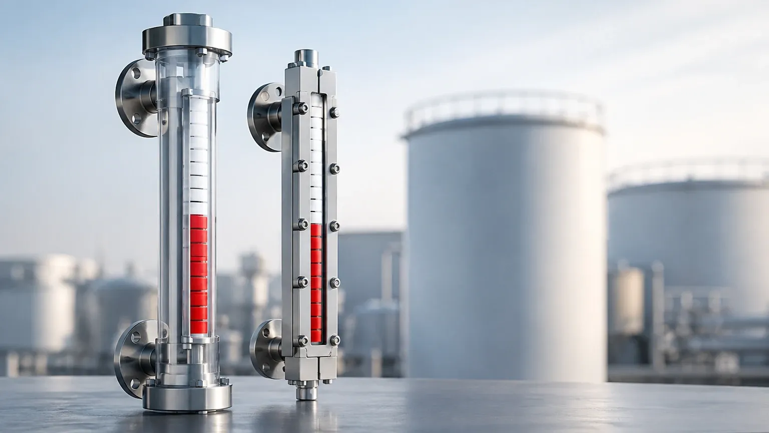
On the exterior of the chamber, a sealed indicator rail (often consisting of magnetic flags or a follower) is mounted. Because of the magnetic field, the external flags flip or the follower moves in direct response to the float's position. This creates a clear, high-contrast visual display without the process fluid ever coming into contact with the viewing glass or the external environment, effectively eliminating the risk of leaks associated with traditional sight glasses.
Technical Specifications and the 10-Meter Benchmark
When specifying a 10 level gauge, the "10" frequently denotes the center-to-center distance or the total measuring length. Standard industrial gauges are often manufactured in sections when they exceed 3 to 4 meters to ensure structural integrity and ease of transport. For a 10-meter application, the gauge is typically constructed in multiple flanged sections.
Material Selection
For industrial applications, the chamber material must be compatible with the process media. Common materials include:
* Stainless Steel (304/316L): The standard for water treatment and general chemical use.
* PTFE/PFA Lined: Used for highly corrosive acids or bases where stainless steel would degrade.
* Special Alloys (Monel, Hastelloy): Reserved for extreme chemical environments or high-temperature steam applications.
Pressure and Temperature Ratings
A high-quality magnetic level gauge can operate in environments ranging from cryogenic temperatures (-196°C) to superheated steam (up to 450°C). Pressure ratings are equally robust, with some units capable of withstanding up to 32 MPa (approx. 4640 psi).
Selection Criteria for Magnetic & Local Level Gauges
Choosing the right gauge involves more than just measuring the height of the tank. Engineers must confirm several variables to ensure the float performs correctly and the chamber survives the process conditions.
1. Fluid Density (Specific Gravity)
The float must be lighter than the fluid to remain buoyant but heavy enough to stay submerged at the correct displacement level. If the fluid density is too low (e.g., liquefied gases), a specialized titanium float may be required. For a 10 level gauge, the float's magnetic strength must be sufficient to penetrate the chamber wall and reach the indicator rail across the entire 10-meter span.
2. Operating Pressure and Temperature
High pressure compresses the float, which can change its buoyancy. Manufacturers must calculate the wall thickness of the float to prevent collapse while maintaining its ability to float. Similarly, high temperatures can affect the magnetic field strength (Curie point), requiring high-temperature magnets.
3. Viscosity and Fouling
If the liquid is highly viscous or contains solids that could cause buildup, the float may become stuck. In these cases, a larger chamber diameter or a specialized coating may be necessary to ensure the float moves freely.
Practical Selection Table
| Feature | Magnetic Level Gauge | Reflex Glass Gauge | Transparent Glass Gauge |
| :— | :— | :— | :— |
| Max Measurement Range | Up to 15m (Multi-section) | ~3m (Limited by glass) | ~3m (Limited by glass) |
| Visibility Distance | Up to 30m+ (High contrast) | < 5m | < 5m |
| Pressure Limit | High (Up to 32 MPa) | Medium (Up to 4 MPa) | Medium (Up to 10 MPa) |
| Hazardous Media | Excellent (Fully sealed) | Risk of glass breakage | Risk of glass breakage |
| Maintenance | Low | High (Cleaning/Gaskets) | High (Cleaning/Gaskets) |
Installation Considerations for Long-Range Gauges
Installing a 10 level gauge requires precision to ensure the magnetic coupling remains consistent and the structure is stable.
Vertical Alignment
The gauge must be installed vertically. A deviation of more than 3 degrees can cause the float to rub against the chamber wall, leading to friction that prevents accurate movement. For 10-meter installations, using a plumb line or laser level is mandatory during the mounting process.
Structural Support
A 10-meter gauge is heavy and subject to vibration or thermal expansion. It is critical to use support brackets (intermediate supports) every 2 to 3 meters. These brackets should allow for thermal expansion while preventing lateral movement that could stress the process nozzles.
Venting and Draining
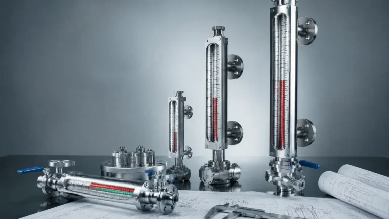
Every local gauge should be equipped with a vent valve at the top and a drain valve at the bottom. This allows for safe commissioning, as air must be bled from the chamber to allow the liquid to enter, and the chamber must be drained for maintenance or float inspection.
Limitations and Operational Risks
While Magnetic & Local Level Gauges are highly reliable, they are not without limitations:
* Magnetic Interference: Nearby high-voltage cables or large ferrous structures can interfere with the magnetic coupling between the float and the indicator.
* Coating and Scaling: If the process fluid leaves deposits (e.g., calcium buildup or heavy oil), the float may eventually stick. Periodic flushing via the drain valve is required.
* Float Damage: If the vessel experiences rapid pressure surges (flashing), the float can be slammed against the top or bottom of the chamber, potentially damaging the internal magnet.
Frequently Asked Questions (FAQs)
Q: Can a 10 level gauge be used for interface measurement?
A: Yes. By calibrating the float weight to sink in the upper (lighter) fluid but float on the lower (heavier) fluid, the gauge can accurately display the interface level between two immiscible liquids, such as oil and water.
Q: How do I verify the gauge is working if I suspect the float is stuck?
A: You can use an external magnet to manually move the indicator flags. If the flags move but do not return to the float's position, the float may be stuck or may have lost its buoyancy. Alternatively, draining the chamber and watching the indicator return to zero is a standard test.
Q: Is it possible to add electronic output to a local gauge?
A: Absolutely. One of the primary advantages of magnetic gauges is that a reed-switch transmitter or a magnetostrictive sensor can be clamped to the outside of the chamber. This provides a 4-20mA or HART signal for the control room without requiring additional tank penetrations.
Q: What is the maximum height for a single-piece gauge?
A: Due to shipping constraints (containers and trucks), single-piece chambers are usually limited to 5 or 6 meters. Anything reaching the 10-meter mark is typically shipped in two sections and joined via flanges on-site.
Conclusion
The implementation of a 10 level gauge provides an indispensable layer of safety and clarity for industrial fluid management. By utilizing the robust principles of magnetic coupling, these instruments overcome the fragility and maintenance intensity of traditional sight glasses. Whether applied in water treatment, chemical processing, or oil and gas, selecting the correct materials and ensuring precise installation are the keys to long-term reliability. For engineers looking to integrate these solutions, focusing on fluid density and structural support will ensure that your local level indication remains accurate across the entire span of your largest vessels.