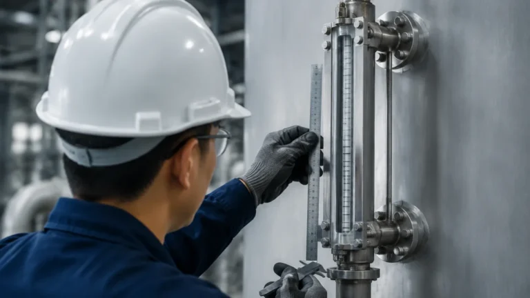
2 Level Gauge
2 Level Gauge
In industrial process control, the requirement to monitor two distinct levels within a single vessel is a common yet complex engineering challenge. Whether the application involves measuring the interface between two immiscible liquids—such as oil and water—or providing a redundant measurement system for safety-critical operations, the "2 level gauge" configuration is an essential tool. This guide explores the principles, selection criteria, and installation requirements for multi-level and interface measurement using Magnetic & Local Level Gauges.
Understanding the Principles of 2 Level Measurement
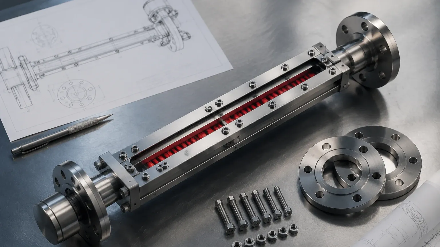
To effectively implement a 2 level gauge system, one must first understand the physics of buoyancy and magnetic coupling that govern these instruments. In a standard magnetic level gauge, a float containing a permanent magnet assembly travels within a bypass chamber connected to the process vessel. As the liquid level rises or falls, the float moves accordingly, and its magnetic field acts upon an external indicator or transmitter.
The Interface Principle
When a gauge is tasked with measuring two levels (interface measurement), the float is engineered based on the specific gravity (SG) of the two liquids. For the float to accurately track the interface—the point where the two liquids meet—it must be designed to sink through the upper, lighter liquid (e.g., oil with an SG of 0.80) and float on the lower, heavier liquid (e.g., water with an SG of 1.00).
This requires precise calibration. If the float is too light, it will stay at the top of the upper liquid; if it is too heavy, it will sink to the bottom of the vessel. The "2 level" functionality is achieved by using either a single float calibrated for the interface or a dual-float system within a single or tandem chamber setup.
Redundancy and Dual-Technology Measurement
Another interpretation of a 2 level gauge system involves redundancy. In high-pressure or hazardous environments, relying on a single measurement technology is often insufficient for Risk Reduction (SIL) requirements. Engineers frequently specify a magnetic level gauge paired with a second technology, such as a guided wave radar (GWR) or a magnetostrictive transmitter, mounted in the same or an adjacent chamber. This provides two independent level readings: one local visual indication and one remote electronic signal.
Technical Selection Criteria for 2 Level Gauges
Selecting the correct instrument requires a detailed analysis of the process media and the physical environment. The following table outlines the primary considerations for different 2 level gauge configurations.
| Feature | Interface (Liquid-Liquid) Gauge | Redundant (Dual Technology) Gauge |
| :— | :— | :— |
| Primary Goal | Measuring the boundary between two fluids. | Providing secondary verification of a single level. |
| Float Design | Weighted specifically between the two SGs. | Standard float calibrated for the process fluid. |
| Min. SG Difference | Typically 0.1 g/cm³ (100 kg/m³). | N/A |
| Indicator Type | Visual flapper or scale. | Visual indicator + Electronic transmitter. |
| Common Media | Oil/Water, Solvent/Water, Acid/Hydrocarbon. | Steam drums, high-pressure storage, toxic chemicals. |
| Chamber Material | 316L SS, Hastelloy, or PTFE-lined. | 316L SS, Titanium, or Carbon Steel. |
Specific Gravity (SG) Sensitivity
The most critical factor in interface measurement is the density difference between the two liquids. A 2 level gauge relies on the float’s displacement volume. If the SG difference is less than 0.1 g/cm³, the float may become unstable, especially if there is turbulence or if the liquids begin to emulsify. In such cases, the "rag layer" (the zone of partial mixing) can lead to inaccurate readings.
Installation and Engineering Considerations
Proper installation is paramount to ensure the longevity and accuracy of Magnetic & Local Level Gauges. Because these systems rely on mechanical movement and magnetic interaction, several environmental factors must be managed.
1. Chamber Alignment and Leveling
The bypass chamber must be installed perfectly vertical. Even a slight tilt can cause the float to rub against the chamber walls, creating friction that leads to "stiction" (the float sticking and then jumping). For 2 level gauge applications involving interface measurement, this is even more critical, as the float is often operating with very narrow buoyancy margins.
2. Venting and Draining
Dual-level systems often handle complex chemical mixtures. Standard practice includes installing vent valves at the top and drain valves at the bottom of the gauge chamber. This allows for the removal of trapped gases or accumulated sediment without de-pressurizing the main vessel. In interface applications, the drain is also used to sample the lower liquid phase.
3. Magnetic Interference
Since the system relies on a magnetic circuit to flip the external indicator flags, the gauge must be kept away from large ferrous structures or high-voltage cables that could generate electromagnetic fields. If two magnetic gauges are installed side-by-side, they must be spaced sufficiently (typically at least 150 mm to 200 mm) to prevent their magnetic floats from interfering with one another.
4. Temperature and Pressure Limits
Standard magnetic gauges can handle temperatures from -196°C to over 400°C and pressures up to 300 bar. However, for a 2 level gauge used in interface service, high temperatures can change the density of the liquids. If the SG of the liquids shifts significantly with temperature, the float may no longer sit accurately at the interface. High-temperature applications may require a "temperature-compensated" float design.
Limitations of 2 Level Gauge Systems
While highly reliable, these systems are not universal solutions. Engineers should be aware of the following limitations:
* Emulsions and Rag Layers: If the two liquids mix to form a thick emulsion layer, the float will seek the average density of that layer, which may not represent the actual separation point.
* Coating and Scaling: In applications like wastewater treatment or crude oil processing, paraffin or scale can build up on the float or the internal chamber walls. This increases the weight of the float or narrows the chamber, eventually causing the gauge to fail.
* Magnetic Particles: If the process fluid contains magnetite or other ferrous particles, they will be attracted to the float's internal magnets. This can weigh down the float or cause it to jam. In these scenarios, a magnetic trap should be installed upstream of the gauge.
Maintenance and Troubleshooting
Routine maintenance for a 2 level gauge is generally low but should include the following steps:
1. Visual Inspection: Regularly check the indicator flags. If they appear faded or are not flipping cleanly, the chamber may need cleaning.
2. Float Integrity: Periodically remove the float (after isolating and draining the chamber) to check for signs of corrosion or collapsed walls due to pressure spikes.
3. Flushing: Use the drain and vent ports to flush the chamber with a compatible solvent if the process media is prone to leaving deposits.
Troubleshooting Common Issues
* Indicator does not move: Check if the float is upside down (the magnetic assembly is usually polarized to one end). Ensure there are no magnetic tools near the indicator.
* Inaccurate Interface Reading: Verify the actual SGs of the liquids. If the process chemistry has changed since the gauge was ordered, the float may need to be re-weighted.
* Transmitter Mismatch: If the local visual level and the remote transmitter level do not match, recalibrate the transmitter. Ensure the transmitter sensor is correctly aligned with the chamber's zero point.
Frequently Asked Questions (FAQs)
Can a 2 level gauge measure three liquids?
Generally, no. A standard magnetic gauge chamber is designed for one float. While it is theoretically possible to have two floats in one chamber, they would likely collide or interfere with each other's magnetic fields. For three-phase measurement (e.g., gas, oil, and water), engineers typically use two separate gauge assemblies mounted at different elevations or combine a magnetic gauge with a guided wave radar.
What is the minimum density difference required for an interface gauge?
For reliable operation, a minimum specific gravity (SG) difference of 0.1 g/cm³ is recommended. While some specialized floats can handle a difference as low as 0.05 g/cm³, these are highly sensitive to temperature fluctuations and turbulence.
Can I add a transmitter to an existing local level gauge?
Yes, one of the primary advantages of Magnetic & Local Level Gauges is their modularity. Most systems allow for the external mounting of a magnetostrictive or reed-switch transmitter without breaking the process seal or interrupting the operation.
How do I choose between a top-mounted and side-mounted 2 level gauge?
Side-mounted gauges are the industry standard for most tanks as they allow for easy access and maintenance. Top-mounted gauges are used when side access is restricted or for underground storage tanks where the level must be measured from the top down.
Does the float need to be replaced if the process liquid changes?
If the new liquid has a significantly different specific gravity (usually a change of more than ±0.05 SG), the float will likely need to be replaced or recalibrated to ensure accuracy. This is especially critical for interface (2 level) applications where the float’s buoyancy is precisely tuned to the liquid boundary.
By following these engineering guidelines and selecting the appropriate float technology, operators can ensure that their 2 level gauge systems provide accurate, maintenance-free service in even the most demanding industrial environments.