3 Level Gauge
3 Level Gauge
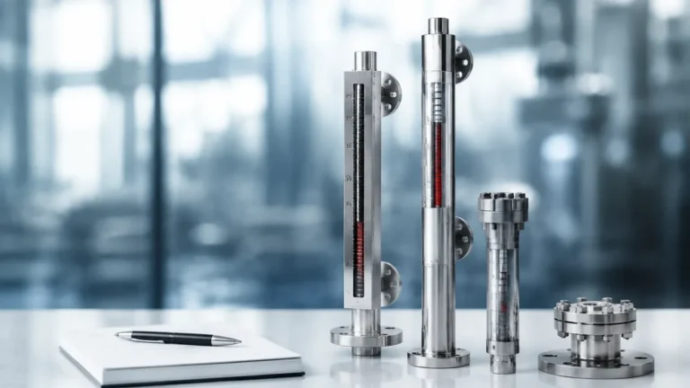
In industrial process control, the term "3 level gauge" typically refers to a level measurement configuration designed to monitor three critical points within a vessel: the high-level alarm point, the normal operating level, and the low-level alarm point. This multi-point monitoring is essential for preventing tank overfills, ensuring pump protection, and maintaining consistent process throughput. While electronic sensors provide data to remote control rooms, Magnetic & Local Level Gauges remain the primary choice for on-site visual verification and safety redundancy.
Welk provides specialized industrial level measurement instruments that translate complex fluid dynamics into reliable, visible data. This guide explores the principles, selection, and application of multi-point level gauges in modern industrial environments.
Measurement Principles of Local Level Gauges
To understand how a 3 level gauge configuration operates, one must first understand the underlying physics of local level indicators. Most industrial applications utilize one of two primary principles: buoyancy-coupled magnetism or direct optical refraction.
Magnetic Coupling Principle
Magnetic level gauges operate on the principle of communicating vessels. The liquid level in the bypass chamber, which is connected to the tank, matches the level inside the tank. Inside this chamber is a float containing a high-strength permanent magnet. As the liquid level rises or falls, the float moves accordingly.
Outside the chamber, a visual indicator—typically consisting of a series of bi-color magnetic flaps or rollers—is mounted. The magnetic field of the float flips these flaps (usually from white to red) as it passes them. This provides a clear, high-contrast visual representation of the liquid level without the need for a glass window that could leak or cloud over time.
Hydrostatic and Optical Principles
For simpler applications, reflex or transparent glass gauges use the optical properties of light. Reflex gauges use a prism-shaped glass that reflects light in the gas space (appearing silvery) and absorbs light in the liquid space (appearing dark). This provides a sharp "3 level" distinction between the phases, though it lacks the remote signaling capabilities often integrated into magnetic systems.
The Role of the 3 Level Gauge in Process Safety
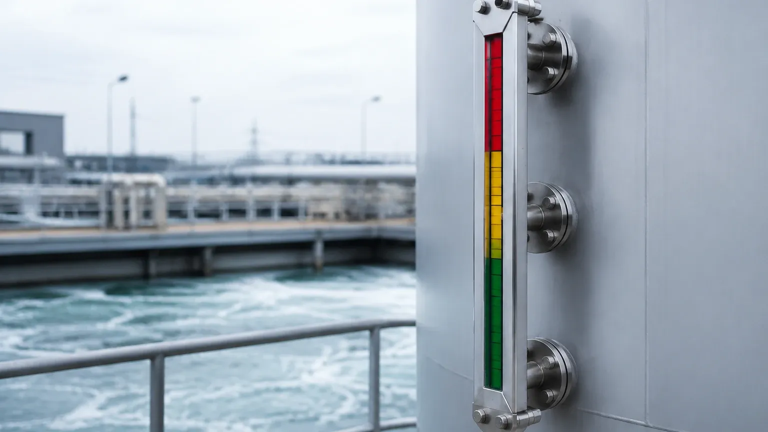
In a standard industrial setup, a 3 level gauge system is calibrated to indicate three specific zones:
1. High Level (HL): The maximum safe filling limit. Reaching this point usually triggers an automated shut-off valve or an audible alarm to prevent overflow.
2. Normal Operating Level (NWL): The target level for steady-state production. Maintaining the fluid at this level ensures optimal residence time and pressure.
3. Low Level (LL): The minimum threshold required to protect downstream equipment. For example, in a pumping system, reaching the LL point triggers a pump cutoff to prevent cavitation and dry running.
By utilizing Magnetic & Local Level Gauges, engineers can mount limit switches directly onto the gauge scale at these three precise heights. This allows the gauge to serve as both a visual indicator and a mechanical safety controller.
Technical Selection Criteria
Choosing the correct gauge requires an analysis of the medium's properties and the vessel's operating environment. The following table outlines the primary considerations for different gauge types used in 3-level monitoring.
Comparison Table: Level Gauge Technologies
| Feature | Magnetic Level Gauge | Reflex Glass Gauge | Transparent Glass Gauge |
| :— | :— | :— | :— |
| Visibility | Excellent (up to 20m distance) | Good (requires proximity) | Moderate (requires backlighting) |
| Pressure Range | Up to 42.0 MPa (420 bar) | Up to 25.0 MPa (250 bar) | Up to 25.0 MPa (250 bar) |
| Temperature Range | -196°C to +450°C | -30°C to +400°C | -30°C to +400°C |
| Maintenance | Low (no glass cleaning) | Moderate (glass etching) | High (cleaning required) |
| Media Suitability | Corrosive, toxic, flammable | Clean, non-viscous | Interface layers, dirty media |
| Redundancy | Can add 4-20mA transmitters | Visual only | Visual only |
Engineering and Installation Considerations
For a 3 level gauge to function accurately, the installation must account for the physical characteristics of the fluid and the vessel geometry.
Connection Types
Most industrial gauges use flange connections (typically DN20, DN25, or DN50) or NPT/BSP threaded connections. For high-pressure steam or chemical applications, welding the gauge directly to the vessel (welding neck) may be required to eliminate potential leak paths.
Venting and Draining
Every bypass level gauge should be equipped with a vent valve at the top and a drain valve at the bottom. This allows for safe commissioning and maintenance. During the initial fill, the vent must be opened to allow air to escape as the liquid enters the chamber, preventing air pockets that would cause false readings.
Specific Gravity (Density) Calibration
The float in a magnetic 3 level gauge must be engineered to match the specific gravity of the process fluid. If the fluid density is 0.8 g/cm³, a float designed for water (1.0 g/cm³) will sit too deep in the liquid, resulting in a level reading that is lower than the actual level. Welk customizes float weights and volumes to ensure accuracy across a wide range of densities, including liquefied gases and heavy oils.
Limitations and Prohibitions
While highly versatile, local level gauges have specific operational boundaries that must be respected to ensure site safety:
* Viscous Media: Extremely thick or sticky liquids can impede the movement of the internal float in magnetic gauges. In such cases, heated jackets or large-diameter chambers are necessary.
* Magnetic Interference: Magnetic gauges should not be installed in close proximity to large motors or high-voltage lines that generate strong electromagnetic fields, as these can interfere with the float-to-flap coupling.
* Particulate Matter: If the process fluid contains magnetic particles (such as iron filings or rust scale), these particles will adhere to the float, increasing its weight and eventually jamming it against the chamber wall. Magnetic filters (traps) should be installed in the bypass line for these applications.
* Mechanical Shock: Glass-based gauges are susceptible to thermal shock. Rapidly introducing high-temperature steam into a cold glass gauge can cause the glass to shatter.
Maintenance and Troubleshooting
A 3 level gauge system is generally low-maintenance, but periodic checks are recommended to ensure the integrity of the seals and the accuracy of the switches.
1. Flap Realignment: Occasionally, external vibrations may cause a few magnetic flaps to flip out of sequence. This is easily corrected by passing a handheld magnet along the indicator rail to reset the flags.
2. Float Inspection: For applications involving scaling or crystallization, the float should be removed and cleaned annually to ensure it remains buoyant and moves freely.
3. Switch Testing: The High and Low limit switches should be manually triggered during scheduled shutdowns to verify that the control logic (alarms/interlocks) is functioning correctly.
Frequently Asked Questions (FAQ)
Q: Can a magnetic level gauge handle interface measurement (e.g., oil on top of water)?
A: Yes. By precisely weighting the float to a density between the two liquids (e.g., 0.85 g/cm³), the float will sink through the oil but float on the water, providing a clear indication of the interface level.
Q: What is the maximum height for a single 3 level gauge?
A: Standard magnetic gauges can be manufactured in single sections up to 6 meters. For taller vessels, gauges are built in multiple sections with staggered connections to provide continuous coverage.
Q: Are these gauges suitable for hazardous areas?
A: Yes. Because the primary indication is mechanical/magnetic, the gauge itself is inherently explosion-proof. If electronic transmitters or switches are added, they can be supplied with ATEX or IECEx certifications for use in Zone 0, 1, or 2 environments.
Q: How do I choose between a reflex gauge and a magnetic gauge for a 3-level setup?
A: If the media is toxic or high-pressure, the magnetic gauge is safer because it contains the fluid within a solid metal pressure chamber. If you need to see the actual color or clarity of the fluid, a transparent glass gauge is the better choice.
Conclusion
Implementing a robust 3 level gauge strategy is a fundamental step in industrial risk management. Whether through the high-visibility rollers of a magnetic indicator or the direct view of a reflex glass system, these instruments provide the essential "ground truth" that electronic systems occasionally lack. For engineers seeking to upgrade their vessel monitoring, exploring the full range of Magnetic & Local Level Gauges ensures a solution that balances accuracy, safety, and long-term durability. By adhering to proper selection and installation guidelines, facilities can maintain precise control over their most critical liquid assets.