4 Level Gauge
4 Level Gauge
In industrial process control, the term "4 level gauge" typically refers to a multi-point level measurement system designed to monitor and trigger actions at four distinct stages within a tank or vessel. These stages are commonly defined as Low-Low (LL), Low (L), High (H), and High-High (HH). Achieving this level of granular monitoring requires robust instrumentation that can provide both visual local indication and automated signal outputs.
For many engineers and plant operators, the most reliable way to implement a 4 level gauge configuration is through the use of Magnetic & Local Level Gauges. These instruments combine the physical laws of buoyancy and magnetism to provide a clear visual interface while allowing for the attachment of multiple switches or transmitters to manage complex automation logic.
Measurement Principles for Multi-Point Monitoring
Before selecting a specific gauge, it is essential to understand the underlying physics that allow an instrument to track four different levels accurately.
The Buoyancy and Magnetic Coupling Principle
Magnetic level gauges operate based on Archimedes' Principle. A float, specifically engineered to match the specific gravity of the process fluid, resides inside a bypass chamber connected to the vessel. Inside this float is a high-intensity permanent magnet. As the liquid level in the tank rises or falls, the float moves accordingly.
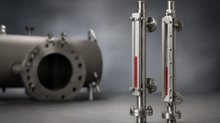
Outside the chamber, a visual indicator—often consisting of bi-color magnetic flaps or rollers—is mounted. The magnet inside the float rotates these flaps 180 degrees as it passes, changing their color (typically from white to red). To transform this into a "4 level gauge" system, magnetic reed switches or a magnetostrictive transmitter are clamped to the outside of the chamber at the four desired setpoints. When the float reaches these points, the magnetic field triggers the switch, sending a signal to a PLC (Programmable Logic Controller) or DCS (Distributed Control System).
Ultrasonic and Hydrostatic Alternatives
While magnetic gauges are the industry standard for high-pressure or high-temperature visual monitoring, other technologies can also serve as a 4 level gauge:
* Ultrasonic Sensors: These use Time-of-Flight (ToF) technology, emitting sound waves that bounce off the liquid surface. The sensor calculates the distance and can be programmed with four software-based relay outputs.
* Hydrostatic Transmitters: These measure the pressure exerted by the liquid column. By calculating the head pressure, the system determines the level and can trigger four discrete alarms via a digital display or controller.
The Role of Magnetic & Local Level Gauges in 4-Point Systems
When a project requires a 4 level gauge setup, magnetic gauges are often preferred because they offer a "fail-safe" visual reference that does not require power. In the event of a total plant power failure, the operator can still walk to the tank and see the exact level, even if the electronic 4-point alarms are offline.
In a typical 4-point configuration:
1. High-High (HH): Acts as an emergency shut-off to prevent tank overfill.
2. High (H): Signals the pump to stop or a valve to close during normal filling.
3. Low (L): Signals the pump to start or a valve to open to replenish the tank.
4. Low-Low (LL): Acts as a dry-run protection for pumps, preventing mechanical damage.
Selection Criteria for a 4 Level Gauge
Choosing the right instrument requires a detailed analysis of the process environment. A mismatch between the gauge and the fluid can lead to float failure or inaccurate readings.
1. Specific Gravity (Density)
The float must be lighter than the liquid it displaces. If the fluid density changes due to temperature fluctuations, the float may sink or sit too high, throwing off the 4-point calibration. For fluids with a specific gravity below 0.5, specialized titanium floats are often required.
2. Pressure and Temperature
Standard magnetic gauges can handle pressures up to 40 bar (580 psi) and temperatures up to 150°C (302°F). However, for high-pressure steam or chemical reactors, custom-engineered chambers capable of 250 bar (3625 psi) and 450°C (842°F) are necessary.
3. Material Compatibility
The wetted parts (the chamber and float) must be resistant to the process medium. Common materials include:
* 304/316L Stainless Steel: Standard for water and general chemicals.
* PTFE/PFA Lining: Required for highly corrosive acids like hydrochloric or sulfuric acid.
* PVC/PP/PVDF: Used for low-pressure, low-temperature corrosive applications.
4. Mounting Configuration
Engineers must decide between side-side, top-bottom, or side-bottom mounting based on the tank's physical constraints. The length of the gauge (the "C-to-C" distance) must cover all four required level points.
Practical Selection Table
| Feature | Magnetic Level Gauge | Ultrasonic Sensor | Hydrostatic Transmitter |
| :— | :— | :— | :— |
| Visual Indication | Direct Local Scale | Digital Display Only | Digital Display Only |
| Power Requirement | None (for visual) | 24V DC / 220V AC | 24V DC Loop Powered |
| Max Operating Temp | Up to 450°C (842°F) | Up to 80°C (176°F) | Up to 120°C (248°F) |
| Max Operating Pressure | Up to 250 bar | Atmospheric | Up to 100 bar |
| Suitability for Foam | Excellent | Poor (Absorbs sound) | Good |
| 4-Point Logic | External Magnetic Switches | Integrated Relays | Controller-based Alarms |

Installation Considerations for 4 Level Gauges
Proper installation is critical to ensure that the four setpoints remain accurate over the lifespan of the equipment.
* Vertical Alignment: Magnetic gauges must be installed perfectly vertical. A tilt of even a few degrees can cause the float to rub against the chamber wall, leading to friction that prevents it from reaching the High-High or Low-Low points.
* Magnetic Interference: Keep the gauge away from large motors, transformers, or high-voltage cables. External magnetic fields can interfere with the coupling between the float and the indicator or switches.
* Isolation Valves: Always install isolation valves between the tank and the gauge. This allows for maintenance and cleaning without draining the entire vessel.
* Switch Positioning: When setting the 4-point levels, ensure there is sufficient distance between the switches to prevent signal overlap. Typically, a minimum of 50 mm (approx. 2 inches) is required between setpoints.
Limitations and Risks
While a 4 level gauge system is highly effective, it is not universal. Certain conditions can compromise performance:
1. High Viscosity: If the liquid is too thick (exceeding 500 cP), the float may move sluggishly, causing a delay in triggering the 4-point alarms.
2. Coating and Scaling: In wastewater or lime slurry applications, material can build up inside the chamber. This "scaling" can eventually trap the float. Regular flushing via a bottom drain valve is necessary.
3. Ferrous Particles: If the process fluid contains iron filings or magnetic particles, they will attach to the internal float magnet, eventually weighing it down or jamming it against the chamber wall. In these cases, a magnetic filter must be installed upstream of the gauge.
Frequently Asked Questions (FAQs)
Q: Can I add a fifth or sixth level point to a 4 level gauge later?
A: Yes, if you are using a magnetic level gauge. You can simply purchase additional magnetic switches and clamp them to the outside of the chamber at the new desired heights. This is one of the primary advantages of magnetic technology over fixed-point sensors.
Q: How do I calibrate the 4 points?
A: For magnetic gauges, calibration is physical. You move the switch up or down the chamber until it aligns with the desired level on the scale. For ultrasonic or hydrostatic systems, calibration is done via the software interface by entering the distance or pressure values corresponding to each level.
Q: What happens if the float leaks?
A: If the float's structural integrity is compromised and fluid enters it, the float will sink. In a 4 level gauge system, this would typically trigger a permanent "Low-Low" alarm. High-quality manufacturers use argon arc welding and pressure-test floats to prevent this.
Project Confirmation: Next Steps
Before finalizing a 4 level gauge procurement, project managers and engineers should confirm the following data points to ensure the system meets the site's operational requirements:
* Center-to-Center (C-to-C) Distance: Confirm the exact distance between the top and bottom process connections. This determines the total measurable range.
* Specific Gravity at Operating Temperature: Fluids expand as they heat up, lowering their density. Ensure the float is designed for the density at the actual operating temperature, not just ambient temperature.
* Switch Rating: Ensure the magnetic switches are rated for the electrical load (e.g., 1A, 220V AC) and the hazardous area classification (ATEX, IECEx, or UL) of the site.
* Environmental Protection: For outdoor installations, ensure the indicator and switch housings are rated at least IP65 or IP67 to prevent moisture ingress.
By following these technical guidelines and prioritizing a robust Magnetic & Local Level Gauges solution, facilities can achieve reliable 4-point monitoring that enhances both process efficiency and plant safety.