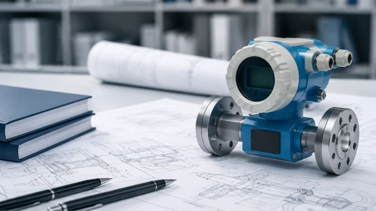
Vegapuls 62
Vegapuls 62
In the landscape of industrial automation, precise level measurement is a cornerstone of process safety, inventory management, and operational efficiency. Among the various technologies available, non-contact radar sensors have emerged as a preferred solution for challenging liquid applications. The Vegapuls 62 represents a specific class of high-frequency radar sensors designed to handle diverse process conditions, ranging from standard storage tanks to complex process vessels involving aggressive chemicals or extreme temperatures.
Understanding the technical nuances, measurement principles, and installation requirements of sensors like the Vegapuls 62 is essential for engineers and procurement professionals. This guide provides a comprehensive technical overview of the technology, its application boundaries, and how it fits into the broader ecosystem of industrial Main Page solutions.
Measurement Principle of Radar Level Sensors
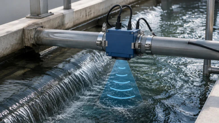
The Vegapuls 62 operates on the pulse radar principle, a subset of Time-of-Flight (ToF) technology. Unlike ultrasonic sensors that rely on sound waves, radar sensors emit short microwave pulses toward the medium being measured. These electromagnetic pulses travel at the speed of light.
The Time-of-Flight (ToF) Mechanism
When a microwave pulse is emitted from the antenna, it travels through the headspace of the vessel until it encounters the surface of the liquid. A portion of the energy is reflected back to the sensor. The electronics within the device measure the time elapsed between the emission of the pulse and the reception of the echo. Since the speed of light is constant, the distance ($D$) to the product surface is calculated using the formula:
$$D = \frac{c \times t}{2}$$
Where:
* c is the speed of light (~300,000 km/s).
* t is the measured transit time.
The level of the liquid is then determined by subtracting the distance ($D$) from the total height of the tank ($H$).
Frequency and Dielectric Constants
The Vegapuls 62 typically operates in the K-band frequency range (approximately 26 GHz). This higher frequency allows for smaller antenna sizes and narrower beam angles compared to lower-frequency C-band (6 GHz) radars.
A critical factor in radar measurement is the dielectric constant (DK or $\epsilon_r$) of the medium. The dielectric constant determines how much energy is reflected back to the sensor. High DK liquids, such as water-based solutions (DK > 20), reflect energy strongly, making them easy to measure. Low DK liquids, such as hydrocarbons or oils (DK 1.5 to 4), reflect less energy, requiring more sensitive electronics and optimized antenna selection to ensure a reliable signal-to-noise ratio.
Technical Specifications and Performance
The Vegapuls 62 is engineered for versatility. Its design focuses on maintaining accuracy even when process conditions fluctuate. Below are the core technical parameters typically associated with this class of instrument:
* Measuring Range: Up to 35 meters (approx. 115 feet).
* Measurement Accuracy: Within ±2 mm, providing high precision for custody transfer or sensitive process control.
* Process Temperature: Standard versions handle -40°C to +200°C, while specialized high-temperature variants can reach up to +450°C.
* Process Pressure: Capable of operating from vacuum (-1 bar) up to 160 bar (16 MPa).
* Frequency: 26 GHz (K-band).
* Beam Angle: Varies by antenna size; typically between 8° and 22°.
Antenna Variants
The choice of antenna is the most significant factor in tailoring the Vegapuls 62 to a specific application.
1. Horn Antenna: The most common choice, available in various diameters (40mm to 95mm). Larger horns provide narrower beams and better focus.
2. Parabolic Antenna: Used for very long ranges or low DK media, as it provides the highest signal gain and the narrowest beam angle.
3. Plastic-Coated Antennas: Designed specifically for highly corrosive liquids (e.g., concentrated acids) where metallic components would degrade.
Selection Criteria for Industrial Level Measurement
Selecting the right radar configuration requires an analysis of the physical environment and the chemical properties of the media. The following table provides a comparison of how different antenna configurations of the Vegapuls 62 perform across common industrial scenarios.
| Application Feature | Horn Antenna (Small) | Horn Antenna (Large) | Parabolic Antenna | Plastic/PTFE Shielded |
| :— | :— | :— | :— | :— |
| Measuring Range | Up to 10m | Up to 20m | Up to 35m | Up to 15m |
| Beam Angle | ~22° | ~10° | ~8° | ~18° |
| Corrosive Media | Moderate | Moderate | Moderate | Excellent |
| Agitated Surfaces | Good | Better | Best | Good |
| Narrow Nozzles | Excellent | Fair | Poor | Good |
| Steam/Condensate | Good | Excellent | Excellent | Good |
Key Evaluation Questions
Before finalizing a specification, project engineers should confirm:
* Vessel Geometry: Are there internal obstructions like agitators, heating coils, or ladders?
* Mounting Position: Is there a nozzle available, and what is its height and diameter?
* Media Dynamics: Does the liquid boil, foam, or have a turbulent surface?
* Vapor Space: Are there high concentrations of dust, steam, or chemical vapors that might attenuate the signal?
Installation Guidelines and Best Practices
Proper installation is paramount to the performance of the Vegapuls 62. Even the most advanced radar sensor will fail if it is poorly positioned.
1. Nozzle Considerations
The radar beam should be able to exit the mounting nozzle without interference. If the nozzle is too long or too narrow, the radar energy will reflect off the nozzle walls, creating a "ringing" effect or a large dead zone at the top of the tank. Ideally, the antenna should protrude slightly past the bottom of the nozzle.
2. Positioning and Alignment
* The 1/3 Rule: For cylindrical tanks with torispherical heads, the sensor should ideally be mounted at 1/3 of the tank radius from the outer wall. This avoids the center of the tank (where multiple reflections can converge) and the tank wall (where the beam might reflect off the side).
* Avoid the Inflow: Never mount the sensor directly over the filling stream. The turbulence and the falling liquid will cause signal noise and erratic readings.
* Vertical Alignment: The sensor must be mounted perpendicular to the liquid surface. Even a few degrees of tilt can significantly reduce the reflected signal strength, especially in low DK applications.
3. False Signal Suppression
Modern radar units like the Vegapuls 62 include software features for "False Signal Suppression" or "Echo Mapping." During commissioning, the sensor can be instructed to record all static reflections (from ladders, pipes, or agitators) while the tank is empty or partially empty. The software then ignores these static echoes in future measurements, focusing only on the moving echo from the liquid surface.

Limitations and Application Constraints
While the Vegapuls 62 is highly robust, it is not a universal solution for every level measurement challenge. Engineers must be aware of the following limitations:
* Heavy Foam: While radar can penetrate thin layers of foam, extremely thick or dense foam (like that found in some fermentation processes) can absorb the radar signal entirely, leading to a "loss of echo" error.
* Extremely Low Dielectric Constants: If a liquid has a DK below 1.4 (such as liquid nitrogen or some liquefied gases), the reflection may be too weak for non-contact radar. In these cases, Guided Wave Radar (GWR) is often a more reliable alternative.
* Internal Obstructions: If an agitator or a large pipe is directly in the path of the beam and cannot be mapped out, the sensor may lock onto that object instead of the liquid surface.
* Build-up: In applications with heavy coating or crystallization, material can build up on the antenna. While the Vegapuls 62 is designed to handle some build-up, excessive accumulation will eventually degrade the signal.
Comparison with Alternative Technologies
When evaluating the Vegapuls 62, it is helpful to compare it against other common technologies found in the Main Page catalog.
Radar vs. Ultrasonic
Ultrasonic sensors are cost-effective but are limited by air temperature, pressure, and vapors. Because ultrasonic waves are mechanical, they require a medium (air) to travel. Changes in air density or the presence of heavy vapors significantly alter the speed of sound, causing errors. Radar, being electromagnetic, is unaffected by vacuum, pressure, or vapor composition.
Non-contact Radar vs. Guided Wave Radar (GWR)
GWR uses a physical probe (cable or rod) to guide the microwave signal. This makes GWR superior for low DK liquids and applications with heavy foam. However, non-contact radar like the Vegapuls 62 is often preferred because it is easier to install, requires no contact with the media (reducing maintenance and corrosion risks), and is not subject to mechanical stresses from moving liquids or agitators.
Frequently Asked Questions (FAQ)
Q: Can the Vegapuls 62 measure solids or powders?
A: While the Vegapuls 62 is primarily optimized for liquids, it can measure some fine-grained solids. However, for most bulk solids applications, a dedicated solids radar (like those with higher 80 GHz frequency) is usually recommended due to the steep angle of repose and dust conditions.
Q: Does the sensor require periodic recalibration?
A: No. Radar sensors are solid-state electronic devices. Once the base parameters (tank height, dielectric constant) are set, the device does not "drift" like mechanical or pressure-based sensors. Periodic verification is recommended for safety-critical loops, but recalibration is rarely necessary.
Q: How does steam affect the measurement?
A: The 26 GHz frequency used by the Vegapuls 62 is largely unaffected by steam. In extreme high-pressure steam applications (like boiler drums), a slight correction factor may be needed for the change in the speed of light through high-pressure vapor, but for most process steam, the effect is negligible.
Q: What happens if the antenna gets wet?
A: Condensation on the antenna is common in many processes. The Vegapuls 62 antenna designs, particularly the encapsulated versions, are shaped to allow droplets to run off, minimizing the impact on the signal.
Conclusion
The Vegapuls 62 remains a benchmark for reliability in the field of non-contact level measurement. By leveraging 26 GHz radar technology, it provides a balance of precision, range, and resistance to harsh process conditions. For engineers looking to implement this technology, success depends on a thorough understanding of the media properties and a disciplined approach to installation.
For more information on selecting the right instrument for your specific application, or to explore alternative sensing technologies such as ultrasonic or hydrostatic transmitters, please visit our Main Page for detailed product specifications and engineering support. Selecting the correct tool is the first step toward a more efficient and safer industrial process.