Non Contact Radar Level Sensor
Non Contact Radar Level Sensor
In the landscape of industrial automation, the non contact radar level sensor has emerged as a primary solution for liquid and solid level measurement. Unlike traditional contact-based methods, such as float switches or guided wave radar, non-contact radar instruments utilize electromagnetic waves to determine the distance to a medium without physical interaction. This characteristic makes them exceptionally durable in corrosive, high-pressure, or hygienic environments where sensor degradation or contamination must be avoided.
As process industries move toward higher precision and reduced maintenance cycles, understanding the underlying physics, selection criteria, and installation nuances of these sensors is essential for engineering and procurement teams. This guide provides a technical overview of non-contact radar technology to assist in selecting the most effective instrumentation for specific industrial applications.
Measurement Principles: How Non-Contact Radar Works
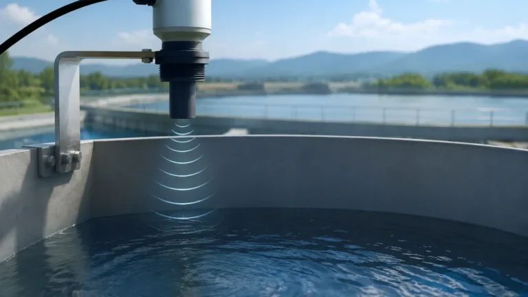
Non-contact radar level sensors operate based on the Time of Flight (ToF) principle. The device, mounted at the top of a vessel, emits a high-frequency microwave signal toward the product surface. This signal reflects off the medium and returns to the sensor antenna. By measuring the time interval between transmission and reception, the sensor calculates the distance to the material surface.
There are two primary modulation techniques used in modern industrial radar sensors: Pulse Radar and Frequency Modulated Continuous Wave (FMCW).
1. Pulse Radar (Time-of-Flight)
Pulse radar sensors emit short microwave pulses at a fixed frequency. The sensor remains in a "receive" mode between pulses to catch the reflected signal. While energy-efficient and suitable for many standard applications, pulse radar often has a lower signal-to-noise ratio compared to FMCW, which can limit its performance in environments with heavy foam or turbulence.
2. Frequency Modulated Continuous Wave (FMCW)
FMCW technology is currently the industry standard for high-precision measurement. Instead of sending discrete pulses, the sensor emits a continuous signal with a frequency that changes over time (a frequency sweep). The reflected signal returns with a frequency shift compared to the signal being transmitted at that exact moment. The difference between these frequencies is directly proportional to the distance. FMCW provides superior resolution and better signal processing capabilities, making it ideal for complex tank geometries.
The Role of Frequency: 26GHz vs. 80GHz
The frequency of a non contact radar level sensor significantly influences its performance, particularly regarding beam angle and signal focus.
* 26GHz Radar: Traditionally the workhorse of the industry, 26GHz sensors are versatile and effective for large tanks. However, they typically have a wider beam angle, which may lead to interference if the tank contains internal obstructions like agitators, ladders, or heating coils.
* 80GHz Radar: The latest generation of sensors utilizes the 80GHz band. The higher frequency allows for a much narrower beam angle (often as low as 3°). A narrower beam is easier to direct past internal obstructions and provides a stronger reflection from the product surface, even in vessels with narrow nozzles or complex internals.
Practical Selection Criteria
Choosing the right sensor requires an analysis of the medium’s properties and the vessel’s physical constraints. The following table outlines key factors to consider during the specification process.
Table 1: Radar Sensor Selection Matrix
| Feature | 26GHz Pulse/FMCW | 80GHz FMCW | Application Note |
| :— | :— | :— | :— |
| Measuring Range | Up to 30m – 70m | Up to 120m | 80GHz is preferred for tall silos. |
| Beam Angle | 8° to 20° | 3° to 8° | Narrower beams avoid internal obstructions. |
| Accuracy | ±3mm to ±5mm | ±1mm | 80GHz offers superior precision for custody transfer. |
| Process Temp. | -40°C to +250°C | -40°C to +200°C (Standard) | Special cooling fins can extend range. |
| Dielectric Constant (εr) | ≥ 1.9 | ≥ 1.4 | Lower DK requires more sensitive electronics. |
| Dust/Vapor Resistance | Moderate | High | Higher frequency penetrates dust more effectively. |
For engineers looking to compare specific models and technical specifications for their facility, it is helpful to Review product options and application support on the Welk Main Page to ensure the hardware matches the chemical compatibility requirements of the site.
Installation Considerations
The reliability of a non contact radar level sensor is heavily dependent on correct physical installation. Even the most advanced 80GHz sensor will fail to provide accurate data if it is mounted in a position that creates signal interference.
1. Mounting Position
The sensor should typically be mounted at 1/6th of the tank diameter away from the side wall. Mounting too close to the wall can result in "ringing" or signal interference from the vessel shell. Conversely, mounting exactly in the center of a domed-top tank can cause multiple reflections to converge at the antenna, leading to false readings.
2. Nozzle Geometry
The radar beam must be able to exit the mounting nozzle without reflecting off the nozzle's inner edges. For 26GHz sensors, the nozzle should be as short as possible. 80GHz sensors are more forgiving due to their narrow beam, often allowing for installation on longer nozzles or through ball valves.
3. Avoiding Obstructions
Ensure the signal path is clear of agitator blades, spray balls, and structural supports. If an obstruction is unavoidable, most modern sensors include "False Echo Suppression" software, which allows the user to map out static reflections so the sensor ignores them during operation.
4. Blind Zone (Blocking Distance)
Every radar sensor has a minimum measuring distance, known as the blind zone or blocking distance, usually ranging from 50mm to 300mm from the antenna face. The maximum level of the medium should never enter this zone, as the sensor cannot process reflections that return too quickly.
Limitations and Environmental Challenges
While highly versatile, non-contact radar is not a "one-size-fits-all" solution. Engineers must account for the following limitations:
* Dielectric Constant (DK): The strength of the reflected radar signal depends on the DK of the medium. Hydrocarbons and oils have low DK values (typically 1.9 to 2.5), resulting in weaker reflections than water-based liquids (DK ≈ 80). If the DK is extremely low (below 1.4), a guided wave radar or a high-sensitivity 80GHz non-contact sensor may be required.
* Heavy Foam: Dense, thick foam can absorb the radar signal entirely, preventing any reflection from reaching the sensor. In applications with constant heavy foam, ultrasonic sensors or contact-based displacement transmitters may be more reliable.
* Extreme Turbulence: Rapidly moving surfaces can scatter the radar signal. This can often be mitigated by increasing the damping (averaging) time in the sensor’s software or using a stilling well.
Maintenance and Troubleshooting
One of the primary benefits of the non contact radar level sensor is the lack of moving parts, which minimizes routine maintenance. However, in applications involving volatile liquids or crystalline solids, the antenna may experience buildup.
* Antenna Cleaning: If the sensor provides a "Low Signal Quality" error, check the antenna face for condensation or material buildup. Many sensors now feature PTFE or PEEK lens covers that are self-cleaning or resist adhesion.
* Signal Loss: If the signal is lost during filling, it is likely due to surface turbulence or dust. Adjusting the signal processing sensitivity or the orientation of the sensor can often resolve this.
Frequently Asked Questions (FAQ)
Q: Can non-contact radar measure through a plastic tank lid?
A: Yes. Since plastic and fiberglass are non-conductive, radar signals can penetrate these materials. This allows for measurement without cutting a hole in the tank, provided the material does not contain metal reinforcement.
Q: Does vacuum affect radar measurement?
A: No. Unlike ultrasonic sensors, which require air as a medium to transmit sound waves, radar uses electromagnetic waves that travel at the speed of light, even in a vacuum. This makes radar ideal for vacuum distillation columns.
Q: How does temperature affect the accuracy?
A: Radar is largely unaffected by temperature fluctuations in the vapor space. However, extreme temperatures can cause the antenna housing to expand or contract slightly. High-quality sensors include internal temperature compensation to maintain accuracy across their rated operating range.
Conclusion
The non contact radar level sensor represents a pinnacle of industrial level measurement technology, offering a combination of high precision and low maintenance. By selecting the appropriate frequency—such as 80GHz for narrow vessels or 26GHz for standard applications—and adhering to strict installation guidelines, process engineers can ensure reliable data even in the most challenging environments. For detailed technical specifications and to explore specific sensor configurations for water treatment, chemical, or oil and gas applications, visit the Main Page for comprehensive product data and engineering support.