Level Switch Capacitance
Level Switch Capacitance
In the field of industrial process control, the level switch capacitance technology remains one of the most versatile and reliable methods for point-level detection. Whether managing bulk solids in a silo or corrosive liquids in a chemical reactor, understanding the nuances of capacitance-based sensing is essential for ensuring operational safety and efficiency. As a professional manufacturer, Welk provides a comprehensive range of level measurement instruments designed to meet the rigorous demands of water treatment, oil and gas, and industrial automation.
This guide explores the underlying physics, application criteria, and installation best practices for capacitance level switches, providing engineers and plant managers with the technical foundation required to select the optimal sensing solution.
Fundamental Measurement Principles
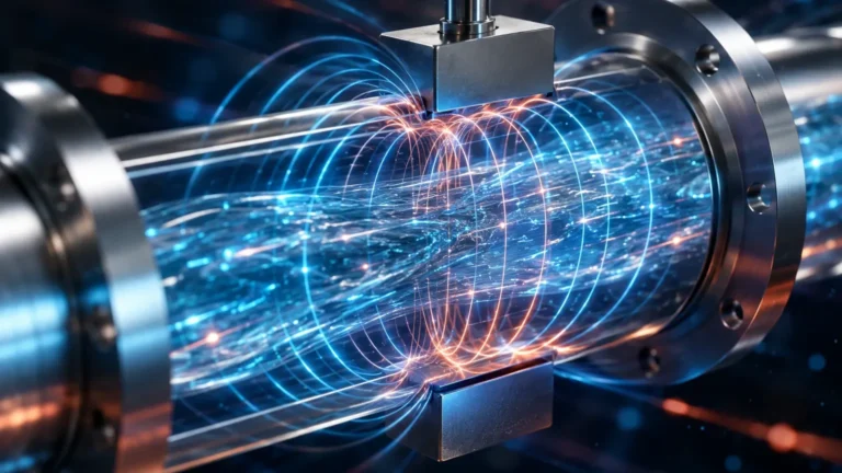
At its core, a level switch capacitance sensor operates as a simple capacitor. A capacitor consists of two conductive plates separated by an insulating material known as a dielectric. In an industrial level sensing application, the sensor probe (the active electrode) acts as one plate, while the vessel wall (the ground electrode) acts as the second plate. If the tank is made of non-conductive material, a secondary ground rod or a reference probe is used.
The ability of this system to store an electrical charge is defined as capacitance (C), which is governed by the formula:
C = ε · (A / d)
Where:
* ε (Epsilon): The dielectric constant of the material between the plates.
* A: The surface area of the electrodes.
* d: The distance between the electrodes.
In a level switch application, the area (A) and distance (d) remain constant. Therefore, the capacitance is directly proportional to the dielectric constant (ε) of the medium surrounding the probe. When the probe is in the air (which has a dielectric constant of approximately 1.0), the measured capacitance is at its lowest. As the process material rises and covers the probe, the air is replaced by a substance with a higher dielectric constant. This causes a measurable increase in capacitance, which the electronics convert into a switching signal (on/off).
The Importance of the Dielectric Constant
The dielectric constant (εr) is a dimensionless number that represents how well a material can store electrical energy. Understanding the εr of your medium is critical for level switch capacitance calibration:
* Low Dielectric Materials (εr < 2.0): Examples include petroleum oils, liquid CO2, and certain dry powders. These require highly sensitive electronics to detect the subtle change in capacitance.
* Medium Dielectric Materials (εr 2.0 – 10.0): Examples include organic solvents and grains.
* High Dielectric Materials (εr > 10.0): Examples include water (εr ≈ 80), acids, and aqueous solutions. These are very easy to detect due to the significant capacitance shift.
RF Admittance vs. Standard Capacitance
While traditional capacitance switches are effective for clean, non-coating materials, industrial environments often involve sticky liquids or slurries that leave a residue on the probe. Standard level switch capacitance sensors may struggle with "false trips" in these scenarios, as the residue is interpreted as the material level still being present.
To solve this, Welk utilizes RF Admittance technology. This is an evolution of capacitance measurement that uses a radio frequency (RF) signal and adds a "Shield" or "Guard" section to the probe.
1. The Active Section: Measures the total signal (material + coating).
2. The Shield Section: Driven at the same voltage and frequency as the active section but is electrically isolated.
By measuring the phase shift and the current flow, the electronics can mathematically cancel out the resistive component caused by the coating, focusing only on the capacitive change caused by the actual bulk material. This ensures high reliability even in high-viscosity applications like wastewater treatment or chemical mixing.
Key Selection Criteria for Industrial Applications
Selecting the right level switch capacitance sensor requires a detailed evaluation of the process environment. Engineers should consult the Main Page of the manufacturer’s technical catalog to review specific model ratings, but the following criteria serve as a primary framework:
1. Material Conductivity and State
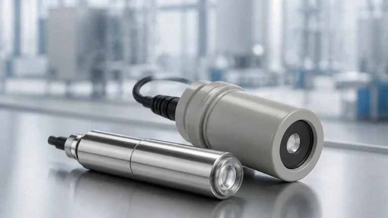
Is the material a liquid, a slurry, or a solid? For conductive liquids, insulated probes (usually coated with PTFE or PFA) are mandatory to prevent a direct short circuit between the probe and the tank wall. For non-conductive dry solids, bare metal probes may be used, provided the material is not abrasive.
2. Temperature and Pressure
Capacitance switches are robust, but the probe insulation and seal must withstand the process conditions. Standard industrial probes often handle temperatures from -40°C to 200°C and pressures up to 40 bar (approx. 580 psi). High-temperature versions with ceramic insulators can extend this range significantly for power plant or kiln applications.
3. Vessel Construction
If the vessel is metal, it serves as the ground reference. If the vessel is plastic, fiberglass (FRP), or concrete, a dual-probe system or a grounding strap is required to complete the circuit.
4. Probe Length and Orientation
Point level switches can be mounted horizontally (through the side of the tank) or vertically (from the top). Vertical mounting allows for adjustable setpoints by changing the probe length, whereas horizontal mounting provides a very precise trigger point at a specific height.
| Application Scenario | Recommended Probe Type | Key Consideration |
| :— | :— | :— |
| Water-based liquids | PTFE Insulated Probe | High sensitivity, anti-corrosive |
| Dry plastic pellets | Bare Stainless Steel | Low dielectric, ensure no static buildup |
| Sticky chemical resin | RF Admittance Probe | Coating rejection is critical |
| High-pressure steam | Ceramic Insulated | Thermal shock and seal integrity |
| Non-metallic tanks | Dual-probe / Ground rod | Establishing a stable reference point |
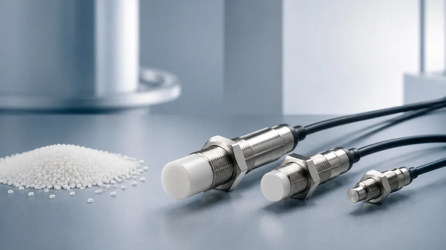
Installation Guidelines and Best Practices
Proper installation is as important as selecting the right technology. To ensure the level switch capacitance sensor performs accurately, follow these engineering guidelines:
* Avoid the Inflow Stream: Never mount a level switch directly in the path of the filling material. The force of the falling material can damage the probe, and the turbulence will cause erratic switching. If the location is unavoidable, install a protective baffle.
* Maintain Clearance: Ensure there is at least 50mm to 100mm of clearance between the probe and the tank wall or any internal structures like ladders or agitators. Proximity to other metal objects can create "stray capacitance" and interfere with the signal.
* Grounding: For reliable operation, there must be a low-resistance electrical path between the sensor housing and the tank. If the tank is painted, the paint must be scraped away at the mounting point to ensure metal-to-metal contact.
* Cable Routing: Use shielded cables for the signal output to prevent electromagnetic interference (EMI) from nearby high-voltage motors or variable frequency drives (VFDs).
* Orientation for Solids: When used for bulk solids, mount the switch at an angle or provide a "roof" over the probe to prevent the weight of the material from bending the probe during tank discharge.
Limitations and Troubleshooting
While highly effective, level switch capacitance technology has specific limitations that must be managed:
1. Changes in Dielectric Constant: If a tank is used for multiple different products with widely varying εr values, the switch may require recalibration between batches. If the εr changes significantly (e.g., switching from oil to water), a standard capacitance switch might fail to trigger or stay triggered.
2. Moisture Content in Solids: In grain or powder applications, a sudden increase in moisture can drastically change the dielectric constant, leading to premature switching.
3. Heavy Buildup: Even with RF Admittance, extreme buildup that bridges the gap between the probe and the tank wall can cause a malfunction. Periodic cleaning of the probe is recommended in high-fouling environments.
Troubleshooting Common Issues
* Switch won't trigger: Check the sensitivity settings. The material may have a lower dielectric constant than anticipated. Ensure the probe is actually being covered by the material.
* Switch stays triggered (False Positive): This is usually caused by conductive coating/buildup on the probe or moisture inside the housing. Check the seals and ensure the "Shield" section of the RF Admittance probe is clean.
* Erratic Switching: Often caused by poor grounding or electrical noise. Verify the tank-to-sensor ground continuity.
Frequently Asked Questions (FAQs)
Q: Can capacitance switches be used for interface detection?
A: Yes. Capacitance switches are excellent for detecting the interface between two non-mixing liquids with different dielectric constants, such as oil (εr ≈ 2.0) and water (εr ≈ 80). The switch is calibrated to trigger only when the higher dielectric material reaches the probe.
Q: Is there a maximum probe length for capacitance switches?
A: For rigid rods, the limit is typically 3 to 4 meters due to weight and potential bending. For deeper tanks or silos, flexible cable probes can be used, extending up to 20 or 30 meters.
Q: How does capacitance compare to ultrasonic switches?
A: Capacitance switches are generally more robust in high-pressure, high-temperature, or dusty environments where ultrasonic signals might be scattered or absorbed. However, ultrasonic sensors are non-contact, which is an advantage for extremely toxic or aggressive media where probe contact is undesirable.
Q: Do I need to recalibrate the switch often?
A: Once set for a specific material, Welk capacitance switches are highly stable. Recalibration is typically only necessary if the process material changes or if the mechanical installation is altered.
For technical specifications and to explore our full range of measurement solutions, including radar and ultrasonic options, please visit our Main Page. Welk provides customized OEM/ODM services to ensure your level measurement systems are accurate, reliable, and cost-effective for any industrial application.