Table Dielectric Constant
Table Dielectric Constant
In the field of industrial process control, the dielectric constant (relative permittivity) is a fundamental physical property that dictates the success of various level measurement technologies. For engineers and technicians, a comprehensive table dielectric constant reference is essential when selecting between radar, capacitance, or ultrasonic sensors. This property, denoted by the Greek letter epsilon (εr), represents the ability of a material to store electrical energy in an electric field compared to a vacuum.
In level measurement, the dielectric constant primarily influences how electromagnetic waves (radar) reflect off the surface of a medium and how electrical charge is stored between a probe and a vessel wall (capacitance). Understanding these interactions is the first step toward ensuring accurate and reliable inventory management.
Understanding Dielectric Constant in Level Measurement
The dielectric constant is a dimensionless value. A vacuum is assigned a value of 1.0, and air is very close at approximately 1.0006. Most industrial liquids and solids have values ranging from 1.2 to 80.0.
Impact on Radar Level Meters
Radar level transmitters, including both non-contact (FMCW or Pulse) and Guided Wave Radar (GWR), rely on the reflection of electromagnetic pulses. When a radar wave traveling through air (εr ≈ 1) hits a medium with a higher dielectric constant, a portion of the energy is reflected back to the sensor. The strength of this reflection is directly proportional to the difference in dielectric constants between the vapor space and the process media.
Materials with high dielectric constants, such as water (εr ≈ 80), provide a very strong signal reflection. Conversely, hydrocarbons like oil or plastic pellets (εr ≈ 1.9 to 2.5) reflect very little energy, making them harder to detect without specialized hardware or configuration.
Impact on Capacitance Level Sensors
Capacitance sensors treat the sensor probe and the tank wall as two plates of a capacitor, with the process material acting as the dielectric. The total capacitance (C) is calculated as $C = ε(A/d)$, where $ε$ is the permittivity of the material. As the level rises, the air (εr = 1) is replaced by the process material (εr > 1), increasing the measured capacitance. If the dielectric constant of the material fluctuates significantly due to temperature or composition changes, the level reading will drift, requiring compensation or a different measurement technology.
Measurement Principles and Dielectric Sensitivity
Before consulting a table dielectric constant, it is important to understand how different technologies handle low-dielectric materials.
1. Non-Contact Radar: These sensors emit signals through the air. If the dielectric constant is below 1.5, the reflection may be too weak to distinguish from background noise. In such cases, high-frequency (80GHz) radar or specialized antennas are required to focus the beam.
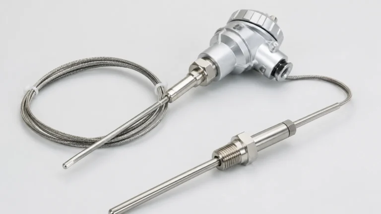
2. Guided Wave Radar (GWR): GWR uses a physical probe (cable or rod) to guide the signal. This concentrates the electromagnetic energy, allowing for reliable measurement of materials with dielectric constants as low as 1.2. GWR is also capable of "interface measurement," where it detects the level of a low-dielectric liquid (like oil) sitting on top of a high-dielectric liquid (like water).
3. Hydrostatic and Ultrasonic: These technologies are generally independent of the dielectric constant. Hydrostatic sensors measure pressure (density-dependent), and ultrasonic sensors measure sound wave Time-of-Flight (density and temperature-dependent). They are often used as alternatives when dielectric properties are unknown or extremely volatile.
Comprehensive Table of Dielectric Constants for Industrial Media
The following table provides the approximate dielectric constants for common industrial materials at room temperature (approximately 20°C / 68°F). These values are intended as a practical engineering reference.
| Material | Dielectric Constant (εr) | Recommended Technology |
| :— | :— | :— |
| Vacuum | 1.0 | N/A |
| Air | 1.0 | N/A |
| Teflon (PTFE) | 2.0 | GWR / Radar |
| Fuel Oil / Diesel | 2.1 | GWR |
| Kerosene | 1.8 – 2.0 | GWR |
| Crude Oil | 2.0 – 2.5 | GWR / Radar |
| Gasoline | 2.0 – 2.2 | GWR |
| Polyethylene Pellets | 1.5 – 2.4 | GWR / High-Freq Radar |
| Asphalt | 2.5 – 3.0 | Radar / GWR |
| Sugar (Granulated) | 1.5 – 2.2 | Radar (High Power) |
| Cement (Powder) | 1.5 – 2.1 | Radar (High Power) |
| Alcohol (Ethyl) | 24.0 | Radar / Ultrasonic |
| Ammonia (Anhydrous) | 15.0 – 25.0 | GWR |
| Acetone | 21.0 | Radar / GWR |
| Methanol | 33.0 | Radar / GWR |
| Glycol | 37.0 | Radar / GWR |
| Water (Distilled) | 80.0 | Any |
| Water (Sea/Tap) | 70.0 – 80.0 | Any |
| Sulfuric Acid | 84.0 | Radar (Corrosion Resistant) |
*Note: Values may vary based on temperature, moisture content, and frequency of the measurement signal. For specific application support, users should consult the Main Page of the equipment manufacturer to verify sensor compatibility.*
Selecting Level Sensors Based on Dielectric Properties
When evaluating a project, the dielectric constant determines the "signal-to-noise" ratio. If you are working with a material at the lower end of the table dielectric constant, follow these selection criteria:
High Dielectric Media (εr > 10)
For materials like water, acids, and aqueous solutions, almost any radar or capacitance sensor will work effectively. The reflection is strong enough that even turbulent surfaces or heavy steam usually do not prevent a reliable reading.
Medium Dielectric Media (εr 3.0 to 10)
Materials like vegetable oils, some solvents, and dry grains fall into this category. Non-contact radar is generally successful here, but antenna selection becomes more important. Larger horn antennas or parabolic reflectors may be needed to capture sufficient signal return.
Low Dielectric Media (εr < 3.0)
This is the most challenging category, common in the petrochemical and plastics industries.
* Guided Wave Radar (GWR): This is the preferred choice. Because the signal is confined to the probe, the energy loss is minimized.
* Stilling Wells: If using non-contact radar, installing the sensor inside a metallic stilling well (a bypass pipe) can help. The pipe acts as a waveguide, preventing the signal from dispersing and increasing the effective reflection from low-εr liquids.
* Coaxial Probes: For GWR, a coaxial probe design offers the highest sensitivity, capable of measuring media with εr as low as 1.2.

Installation Considerations for Low Dielectric Applications
When the dielectric constant is low, the installation environment becomes critical. Small errors that might be ignored in water applications can cause total signal loss in hydrocarbon applications.
1. Bottom Reflection (The "Ghost" Echo): In low-dielectric liquids, the radar signal may pass through the liquid, hit the bottom of the tank, and return to the sensor. If the tank is nearly empty, the sensor might confuse the tank bottom with the liquid surface. Advanced sensors use "Bottom Logic" or "Tank Map" functions to ignore these reflections.
2. Obstructions: Internal tank structures like ladders, agitators, or heating coils create parasitic reflections. For low-dielectric media, these "noise" signals might be stronger than the actual product reflection. Ensure a clear Line of Sight (LoS) or use a GWR probe to bypass obstructions.
3. Nozzle Geometry: For non-contact radar, the mounting nozzle should be as short and smooth as possible. For low εr materials, signal attenuation within a long nozzle can drown out the weak reflection from the product surface.
4. Probe Length (GWR): For Guided Wave Radar, ensure the probe reaches the minimum level required. In materials with εr < 1.6, the "dead zone" at the bottom of the probe may increase, as the signal requires more surface area to produce a detectable pulse.
Limitations and Troubleshooting
While the table dielectric constant is a vital tool, engineers must be aware of dynamic process conditions that can alter these values.
* Temperature Effects: For most liquids, the dielectric constant decreases as temperature increases. If a process operates at extreme temperatures (e.g., >200°C / 392°F), a material that is easily measurable at room temperature may become difficult to track at operating temperature.
* Moisture in Solids: For dry powders like cement or fly ash, a small increase in moisture content can dramatically increase the dielectric constant. This usually makes measurement easier, but it can cause calibration errors in capacitance-based systems.
* Foam and Turbulence: Foam is a mixture of air (εr = 1) and liquid. Depending on the density and dielectric of the liquid, foam may either absorb the radar signal, reflect it prematurely, or be transparent to it. Generally, dense, wet foam reflects the signal, while dry, airy foam is transparent.
Frequently Asked Questions (FAQ)
Q: Can I use radar to measure the level of liquid nitrogen or liquefied natural gas (LNG)?
A: Yes, but these have extremely low dielectric constants (εr ≈ 1.4 to 1.7). Guided Wave Radar with a coaxial probe or high-frequency non-contact radar with a stilling well is typically required.
Q: Why does my capacitance sensor drift when the weather changes?
A: Capacitance sensors are sensitive to the dielectric of the entire space between the probe and the wall. If the humidity in the vapor space changes significantly, or if moisture condenses on the probe, the sensor will perceive this as a change in level. Radar is generally immune to these atmospheric changes.
Q: What is the minimum dielectric constant for non-contact radar?
A: Most modern industrial radars can handle εr down to 1.4 or 1.5, provided the surface is calm and the installation is optimized. Below 1.4, GWR is almost always recommended.
Q: Does the dielectric constant affect ultrasonic sensors?
A: No. Ultrasonic sensors use sound waves, which are mechanical vibrations. They are affected by air temperature, pressure, and turbulence, but they do not "see" the dielectric properties of the material.
Conclusion
Selecting the right level measurement technology requires a balance between process conditions and material properties. The table dielectric constant serves as a primary filter in this selection process. By identifying whether a medium is high-dielectric (easy to measure) or low-dielectric (requires specialized equipment), engineers can avoid costly installation errors and ensure long-term accuracy. For complex applications involving multi-phase liquids or extreme powders, always verify the sensor specifications against the dielectric requirements of the specific process media.