Fertilizer Mixing Tank
Fertilizer Mixing Tank
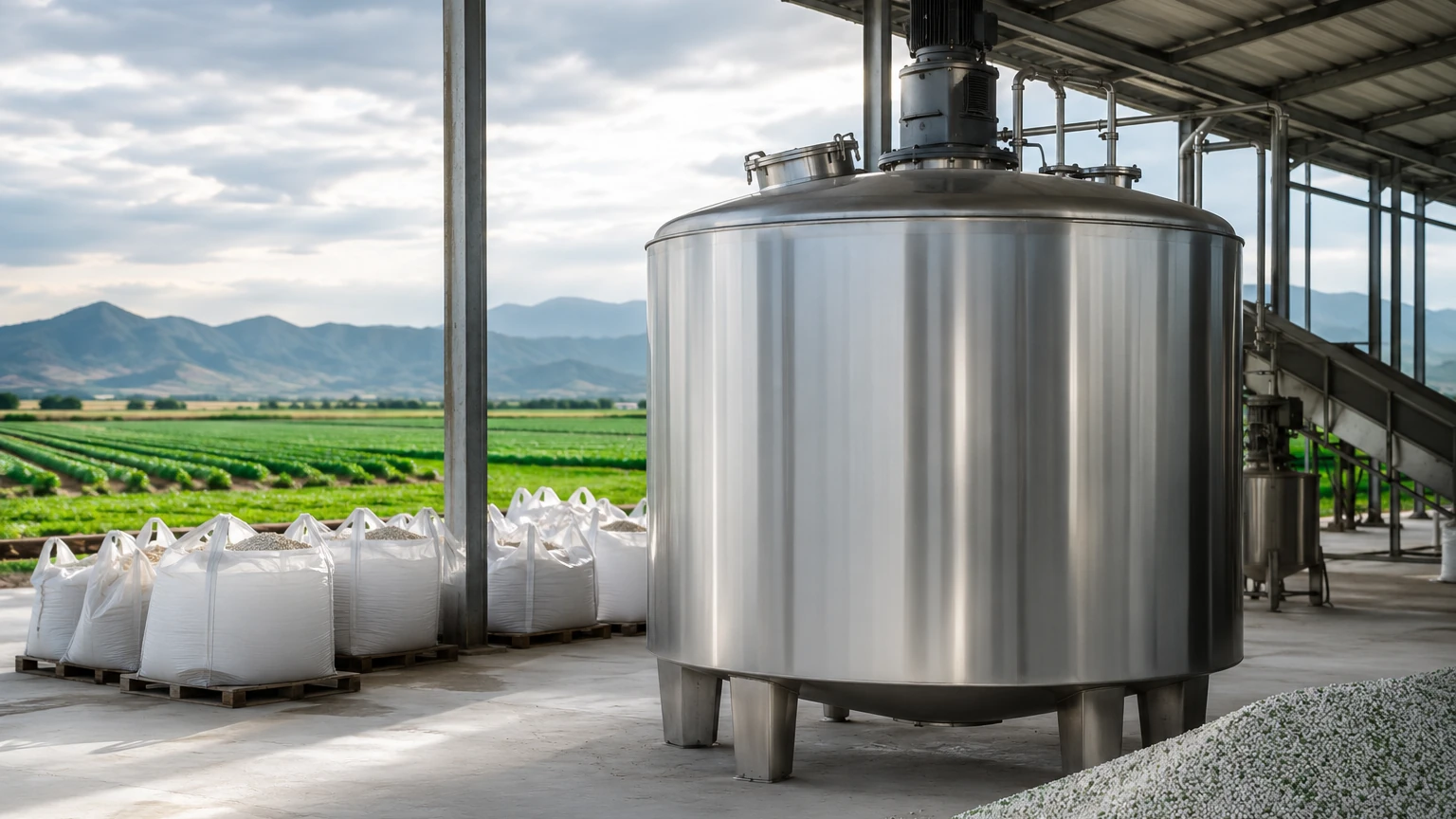
In modern industrial agriculture and chemical processing, the fertilizer mixing tank serves as the central hub for nutrient management. These vessels are designed to blend various chemical components—primarily nitrogen, phosphorus, and potassium (NPK)—along with micronutrients and water to create precise liquid fertilizer formulations. Effective operation of a fertilizer mixing tank requires not only robust mechanical design but also sophisticated instrumentation to ensure accurate dosing, inventory management, and process safety.
Level measurement is perhaps the most critical monitoring parameter within these tanks. Because fertilizer production involves expensive raw materials and highly corrosive chemicals, precise level control prevents overfilling, ensures correct mixing ratios, and protects downstream equipment from running dry. This guide explores the technical requirements for monitoring a fertilizer mixing tank and the engineering principles used to select the appropriate level measurement technology.
Understanding the Environment of a Fertilizer Mixing Tank
Before selecting instrumentation, engineers must account for the specific physical and chemical conditions inside the tank. Fertilizer mixing is rarely a static process; it involves several variables that can interfere with sensor accuracy:
1. Chemical Corrosivity: Many liquid fertilizers are acidic or highly alkaline. Standard stainless steel may not suffice, necessitating the use of specialized plastics (like PTFE or PVDF) or high-grade alloys for wetted parts.
2. Agitation and Turbulence: Mixing tanks are equipped with internal impellers to ensure a homogeneous blend. This creates a turbulent surface and potential vortexes, which can confuse non-contact level sensors.
3. Foaming: The chemical reactions during mixing, or the presence of surfactants, often result in a layer of foam. Foam can absorb ultrasonic signals or cause false echoes in certain radar frequencies.
4. Crystallization and Scaling: As water evaporates or temperatures drop, fertilizer salts may crystallize on the tank walls and the sensor face, leading to "bridging" or signal attenuation.
Measurement Principles for Fertilizer Tanks
To choose the right instrument, it is essential to understand the physics behind the most common measurement technologies used in the industry.
Ultrasonic Level Measurement
Ultrasonic sensors emit high-frequency sound pulses that travel through the air, reflect off the liquid surface, and return to the transducer. The time-of-flight is used to calculate the distance.
* Suitability: Best for atmospheric tanks with relatively calm surfaces and no heavy foam.
* Limitation: In a fertilizer mixing tank, heavy vapors or significant temperature gradients can alter the speed of sound, leading to inaccuracies. If the tank is pressurized, ultrasonic technology cannot be used.
Radar Level Measurement (Non-Contact)
Radar sensors use high-frequency electromagnetic waves (typically 26GHz or 80GHz). These waves travel at the speed of light and are reflected by the dielectric constant of the fertilizer.
* Suitability: Highly accurate and unaffected by temperature, pressure, or vapor. 80GHz radar is particularly effective in fertilizer applications because its narrow beam can be directed to avoid internal agitators.
* Limitation: Very low dielectric liquids (though most fertilizers have sufficient dielectric properties) and extremely thick, dense foam can pose challenges.
Hydrostatic Pressure Measurement
This principle relies on the relationship between the height of the liquid and the pressure exerted at the bottom of the tank ($P = \rho gh$). A pressure transmitter is mounted at or near the bottom of the tank.
* Suitability: Excellent for deep tanks and unaffected by surface foam or turbulence.
* Limitation: Changes in the density (specific gravity) of the fertilizer mix will directly affect the level reading. Since different fertilizer batches have different densities, the sensor must be recalibrated or compensated if the density is not constant.
Magnetic Level Gauges
A magnetic level gauge uses a float containing an internal magnet that moves with the liquid level inside a bypass chamber. Outside the chamber, magnetic flags or a transmitter track the float's position.
* Suitability: Provides a clear visual indication for operators on the plant floor and is immune to foam and dielectric changes.
* Limitation: Requires external piping (bypass) which may be prone to clogging if the fertilizer tends to crystallize.
Practical Selection Criteria
When specifying a level sensor for a fertilizer mixing tank, engineers should use the following table to compare technologies based on typical application requirements.
| Feature | Ultrasonic | Radar (80GHz) | Hydrostatic | Magnetic Gauge |
| :— | :— | :— | :— | :— |
| Accuracy | ±0.25% of range | ±1 mm to ±2 mm | ±0.1% to ±0.5% | ±5 mm |
| Corrosion Resistance | High (Plastic bodies) | High (PTFE faces) | Medium (Requires Alloy) | High (Plastic/Alloy) |
| Foam Tolerance | Low | Moderate to High | Excellent | Excellent |
| Agitation Tolerance | Low | High (Narrow beam) | Excellent | Excellent |
| Maintenance | Low | Very Low | Moderate | Moderate (Cleaning) |
| Relative Cost | Low | Moderate to High | Low to Moderate | Moderate |
For comprehensive technical specifications and to Review product options and application support, consulting a specialist manufacturer like Welk ensures that the selected device matches the specific chemical compatibility of your fertilizer blend.
Installation Considerations and Best Practices
Proper installation is as important as selecting the right technology. For a fertilizer mixing tank, follow these engineering guidelines:
1. Avoiding the Agitator
If using non-contact sensors (Radar or Ultrasonic), the sensor must be positioned so the signal beam does not intersect the path of the mixing blades. Even with "false echo suppression" software, a direct hit on a moving blade will cause signal noise. Position the sensor at least 200 mm from the tank wall but away from the center where the vortex is deepest.
2. Stilling Wells
In cases of extreme turbulence or heavy foam, a stilling well (a vertical pipe installed inside the tank) can be used. The sensor measures the level inside the pipe, which remains calm even while the rest of the tank is being agitated. For fertilizer applications, the stilling well must have vent holes to equalize pressure and be made of a material compatible with the chemicals.
3. Mounting Nozzles
Ensure that the mounting nozzle height does not interfere with the sensor’s "dead zone" (the area immediately below the sensor where it cannot measure). For 80GHz radar, the nozzle should be as short as possible to prevent internal reflections.
4. Chemical Compatibility
Fertilizers often contain nitrates, phosphates, and potassium chlorides. These can be highly aggressive toward metals. Ensure all wetted parts, including gaskets and diaphragms, are specified in materials such as 316L Stainless Steel, Hastelloy, or PVDF. For the Main Page of your instrumentation strategy, always verify the pH levels of the liquid being mixed.
Limitations and Risks
While modern instrumentation is highly reliable, there are inherent risks in fertilizer mixing environments:
* Density Fluctuations: If you are using hydrostatic transmitters, a change from a 10-10-10 NPK mix to a 20-0-0 mix will change the liquid density. Without adjusting the scaling in the PLC, your level reading will be incorrect.
* Vapor Clouds: Concentrated liquid fertilizers can off-gas, creating dense vapor clouds. While radar penetrates these, ultrasonic signals may be reflected prematurely, leading to a "tank full" false alarm.
* Build-up: If the tank is allowed to dry, fertilizer crust can form on the sensor. Periodic inspection and cleaning are necessary to maintain long-term accuracy.
Frequently Asked Questions (FAQ)
Q: Can I use a float switch for high-level alarms in a fertilizer tank?
A: Yes, but it is risky. Fertilizer salts can crystallize on the pivot point or the float itself, causing it to stick. Non-contact radar is generally preferred for high-level overfill protection in these environments.
Q: What is the best material for a level sensor in a phosphoric acid mixing tank?
A: Phosphoric acid is highly corrosive. PVDF or PTFE-coated sensors are typically recommended. If using a pressure transmitter, a Tantalum or Gold-plated diaphragm may be required for longevity.
Q: How do I handle the "Vortex Effect" during high-speed mixing?
A: During high-speed mixing, the level at the center of the tank drops while the level at the walls rises. It is best to mount the level sensor approximately 1/3 of the way from the wall to the center to get a representative average level, or use a stilling well to eliminate the vortex effect on the measurement.
Q: Is 80GHz radar better than 26GHz for fertilizer tanks?
A: Generally, yes. The 80GHz frequency allows for a much smaller antenna and a narrower beam angle (as small as 3 degrees). This makes it much easier to avoid internal obstructions like agitator shafts, ladders, and baffles commonly found in mixing tanks.
Conclusion
Selecting the right level measurement solution for a fertilizer mixing tank is a balance between chemical compatibility, physical process conditions, and budget. While ultrasonic sensors offer a cost-effective solution for simple storage, the complexities of active mixing often necessitate the use of 80GHz radar or robust hydrostatic transmitters. By understanding the measurement principles and accounting for the unique challenges of the fertilizer industry, engineers can ensure a safe, efficient, and highly accurate production process.