Feed Gas Compressor Ko Drum Definition
Feed Gas Compressor Ko Drum Definition
In the realm of industrial gas processing and petrochemical engineering, the integrity of rotating equipment is paramount. Among the most critical components in a compression string is the knock-out drum. Understanding the feed gas compressor ko drum definition is essential for engineers, plant operators, and maintenance professionals who must ensure that gas streams are properly conditioned before entering high-velocity compressor stages. This article provides a comprehensive technical overview of the KO drum’s role, the physics of liquid separation, and the specialized level measurement technologies required to protect these high-value assets.
Understanding the Feed Gas Compressor KO Drum Definition and Purpose
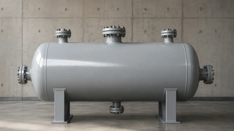
A feed gas compressor knock-out (KO) drum, also frequently referred to as a suction scrubber or inlet separator, is a pressure vessel installed upstream of a compressor stage. Its primary function is to remove entrained liquids—such as water, hydrocarbons, or condensed lubricants—from the gas stream.
The technical definition centers on the concept of "mechanical separation." Compressors are designed to handle compressible fluids (gases). Liquids, however, are essentially incompressible. If a significant volume of liquid, known as a "slug," enters a centrifugal or reciprocating compressor, the results are often catastrophic. Potential consequences include shattered impellers, bent connecting rods, damaged valves, and severe casing failures. Therefore, the KO drum acts as the final line of defense, ensuring that the gas entering the compressor meets the required dryness specifications.
Beyond mechanical protection, the KO drum also serves to:
* Prevent corrosion in downstream piping and compressor internals.
* Reduce the risk of fouling on heat exchanger surfaces.
* Stabilize the flow profile of the gas stream before it reaches the compressor suction nozzle.
Operating Principles of Liquid Separation in KO Drums
The separation of liquids from gas within a KO drum relies on three primary physical principles: gravity, impingement, and centrifugal force.
Gravity Settling
As the gas enters the larger volume of the KO drum, its velocity drops significantly. According to Stokes' Law, when the upward velocity of the gas is lower than the settling velocity of the liquid droplets, the droplets will fall to the bottom of the vessel. The vessel must be sized to provide sufficient "residence time" for this settling to occur.
Impingement (Mist Eliminators)
Small droplets that are too light to settle by gravity alone are captured using mist eliminators or demister pads. These are typically mesh pads or vane packs located near the gas outlet. As the gas weaves through the mesh, the liquid droplets collide with the wire surfaces, coalesce into larger drops, and eventually fall to the liquid collection section at the bottom.
Centrifugal Separation
In some designs, the inlet nozzle is oriented tangentially to the vessel wall. This creates a cyclonic motion, using centrifugal force to throw heavier liquid particles against the wall, where they drain downward.
Level Measurement Principles for KO Drums
Accurate level measurement is the most critical aspect of KO drum operation. If the liquid level rises too high, it can be re-entrained into the gas stream (carry-over), defeating the purpose of the drum. Conversely, if the level is too low, gas might escape through the liquid drain line (blow-by).
Before selecting an instrument, it is important to understand the measurement principles employed by modern industrial sensors.
Guided Wave Radar (GWR)
Guided Wave Radar operates on the principle of Time Domain Reflectometry (TDR). A low-energy electromagnetic pulse is sent down a probe (waveguide). When the pulse hits the liquid surface, a portion of the energy is reflected back to the transmitter due to the change in the dielectric constant (εr) between the gas and the liquid. The device measures the time-of-flight to calculate the distance. GWR is highly effective in KO drums because it is unaffected by changes in gas pressure, temperature, or density.
Magnetic Level Gauges (MLG)
This technology uses a float containing an internal magnet assembly that moves up and down a bypass chamber as the liquid level changes. Outside the chamber, a series of magnetic flags or a follower indicates the level visually. For automated control, a reed chain or magnetostrictive transmitter can be strapped to the outside of the chamber. This provides a robust, mechanical backup to electronic sensors.
Hydrostatic Pressure Measurement
Hydrostatic sensors measure the pressure exerted by the liquid column (P = ρgh). By comparing the pressure at the bottom of the vessel to the vapor space pressure (differential pressure), the level can be inferred. While reliable, this method requires accurate knowledge of the liquid's density, which can vary with temperature and composition in feed gas applications.
Selection Criteria for KO Drum Level Instrumentation
Choosing the right instrumentation requires balancing accuracy, reliability, and the specific process conditions of the feed gas. For a detailed review of available hardware and engineering support, professionals often consult the Main Page of specialized manufacturers like Welk to compare technical specifications.
| Feature | Guided Wave Radar | Magnetic Level Gauge | Differential Pressure (DP) |
| :— | :— | :— | :— |
| Accuracy | High (±2-5 mm) | Medium (±5-10 mm) | Medium (Depends on Density) |
| Pressure Range | Up to 400 bar | Up to 250 bar | Very High |
| Temperature Range | -196°C to +450°C | -196°C to +400°C | Process Dependent |
| Maintenance | Low (No moving parts) | Low (Periodic cleaning) | Medium (Impulse line clogging) |
| Interface Detection | Excellent | Possible (Float density) | Difficult |
When evaluating the feed gas compressor ko drum definition in a practical project, consider the dielectric constant of the liquid. If the liquid is a light hydrocarbon with a low dielectric constant, a Guided Wave Radar with a coaxial probe may be necessary to ensure a strong signal reflection.

Installation Considerations and Safety Best Practices
The installation of level instruments on a KO drum must adhere to strict engineering standards to ensure the safety of the compressor.
1. Redundancy and Voting Logic: For critical compressor protection, a single level switch is rarely sufficient. Most modern plants utilize a 2oo3 (two-out-of-three) voting logic for High-High level shutdowns. This prevents a single instrument failure from causing either a nuisance trip or a failure to trip during a genuine liquid surge.
2. Stilling Wells and Cages: In vessels with high turbulence or foaming, GWR probes should be installed in stilling wells or external bypass cages. This provides a calm surface for measurement and protects the probe from mechanical stress.
3. Nozzle Placement: Level instruments should be located away from the inlet nozzle to avoid the direct impact of incoming gas and liquid, which can cause false readings or mechanical damage.
4. Nozzle Length: For radar installations, the nozzle height and diameter must be checked against the "dead zone" or "blocking distance" of the sensor to ensure the instrument can measure all the way to the top of the vessel if necessary.
Common Risks and Limitations
Despite advanced technology, several factors can interfere with accurate level detection in KO drums:
* Foaming: If the feed gas contains surfactants or contaminants, foam may form on the liquid surface. Ultrasonic sensors often fail in these conditions as the foam absorbs the sound waves. GWR is generally more resistant but may require specific configuration.
* Paraffin or Scale Buildup: In some gas streams, waxes or scales can coat the probes of contact-type instruments. Magnetic level gauges may suffer from "stuck floats" if debris enters the bypass chamber. Regular blow-down of the chambers is required.
* Vapor Space Density: At very high pressures, the density of the gas in the vapor space can increase to the point where it slows down the radar signal. High-end radar transmitters include "Vapor Compensation" features that use a reference reflector to calibrate the signal speed in real-time.
Maintenance and Troubleshooting
A proactive maintenance schedule is vital for the continued protection of the compressor.
* Visual Inspection: Regularly check for leaks at flanges and gaskets, especially in high-pressure hydrogen or sour gas service.
* Proof Testing: For Safety Instrumented Systems (SIS), periodic proof testing of the High-High level trip is mandatory to meet SIL (Safety Integrity Level) requirements.
* Cleaning: If the gas stream is "dirty," bypass chambers and GWR probes should be inspected for buildup during scheduled plant turnarounds.
Frequently Asked Questions (FAQs)
Q: What is the difference between a KO drum and a Flash Drum?
A: While both are separators, a KO drum is specifically designed to protect downstream equipment (like a compressor) by removing entrained droplets. A flash drum is designed to encourage a phase change by dropping the pressure of a liquid stream to "flash" off vapors.
Q: Can I use non-contact ultrasonic sensors on a feed gas KO drum?
A: Generally, no. Ultrasonic sensors are sensitive to gas composition, pressure, and temperature changes. In a pressurized feed gas environment, the speed of sound varies significantly, leading to large measurement errors. Radar or displacement-based technologies are preferred.
Q: Why is the "High-High" level setpoint so critical?
A: The High-High (HH) setpoint is the final trigger that shuts down the compressor. It is positioned to provide enough volume between the HH level and the gas outlet to account for the time it takes for the compressor to come to a complete stop, preventing any liquid from being sucked into the intake during the coast-down period.
Q: How does liquid density affect Guided Wave Radar?
A: Unlike hydrostatic pressure sensors, GWR is independent of liquid density. It only cares about the dielectric constant. This makes it ideal for applications where the composition of the condensed liquids may change over time.
By strictly adhering to the feed gas compressor ko drum definition and implementing robust level measurement strategies, industrial facilities can significantly extend the lifespan of their compression equipment and minimize the risk of costly unscheduled downtime.