Calibrate Pressure Sensor
Calibrate Pressure Sensor
In the landscape of industrial automation and process control, the ability to accurately calibrate pressure sensor units is fundamental to maintaining system integrity, safety, and efficiency. Pressure sensors, including those used in hydrostatic level measurement, are subject to physical stresses, environmental fluctuations, and electronic drift over time. Without a rigorous calibration regime, the data provided by these instruments can lead to suboptimal process performance or, in critical cases, equipment failure.
As a professional manufacturer of industrial level measurement instruments, Welk provides high-precision solutions across various sectors. Understanding the underlying principles and the practical steps required to maintain these sensors is essential for engineers and technicians tasked with process optimization. This guide provides a comprehensive technical overview of the calibration process, specifically tailored for B2B applications in water treatment, chemical processing, and oil and gas industries.
Understanding Pressure Measurement Principles
Before detailing the steps to calibrate pressure sensor hardware, it is necessary to understand how these devices convert physical force into an electrical signal. Most industrial pressure transmitters utilize one of two primary sensing technologies: piezoresistive or ceramic capacitive.
Piezoresistive Sensing
Piezoresistive sensors consist of a diaphragm with integrated strain gauges. When pressure is applied, the diaphragm deforms, causing a change in the electrical resistance of the strain gauges. This change is proportional to the applied pressure. These sensors are highly sensitive and widely used in hydrostatic level transmitters. However, they are susceptible to temperature fluctuations, necessitating a compensation circuit or a formal calibration process to account for thermal drift.
Ceramic Capacitive Sensing
Capacitive sensors utilize a sensing diaphragm and a ceramic substrate to form a variable capacitor. As pressure moves the diaphragm, the capacitance changes. These sensors are known for their robustness and resistance to overpressure conditions. Because they rely on physical displacement, mechanical wear or material fatigue over years of service can shift the "zero" point, making regular calibration a necessity.
The Relationship to Level Measurement
In many applications, pressure sensors are used to determine the level of a liquid in a tank. This is based on the hydrostatic principle: $P = \rho \cdot g \cdot h$, where $P$ is pressure, $\rho$ is the density of the fluid, $g$ is gravity, and $h$ is the height of the liquid. When you calibrate pressure sensor units in this context, you are ensuring that the pressure reading correctly reflects the liquid column height. Any error in pressure measurement translates directly into a level measurement error.
Why Calibration is Mandatory
Calibration is the process of comparing the output of a device under test (DUT) against a reference standard of known accuracy. In industrial environments, several factors necessitate this process:
1. Sensor Drift: Electronic components and mechanical diaphragms change slightly over time due to aging, leading to a gradual shift in output.
2. Environmental Stress: Exposure to extreme temperatures, vibration, and pressure spikes can alter the sensor's calibration curve.
3. Regulatory Compliance: Many industries, particularly chemical and pharmaceutical, require documented calibration traces to meet ISO or safety standards.
4. Process Efficiency: In accurate dosing or custody transfer, even a 0.5% error can result in significant financial losses over a fiscal year.
Essential Equipment for Calibration
To perform a professional-grade calibration, specific tools are required to ensure the reference standard is significantly more accurate (typically 4 times more accurate) than the sensor being tested.
* Pressure Source: A manual hand pump (pneumatic for low pressure, hydraulic for high pressure) or a deadweight tester for primary standards.
* Reference Gauge: A high-precision digital master gauge that provides the "truth" for the comparison.
* Multimeter or Process Calibrator: To measure the output signal of the sensor, usually 4-20 mA or 0-10 VDC.
* HART/Fieldbus Communicator: For smart transmitters, a communicator is needed to adjust the internal digital parameters (Zero Trim and Sensor Trim).
* Power Supply: A stable 24V DC source to power the transmitter during the bench test.
Step-by-Step Procedure to Calibrate Pressure Sensor
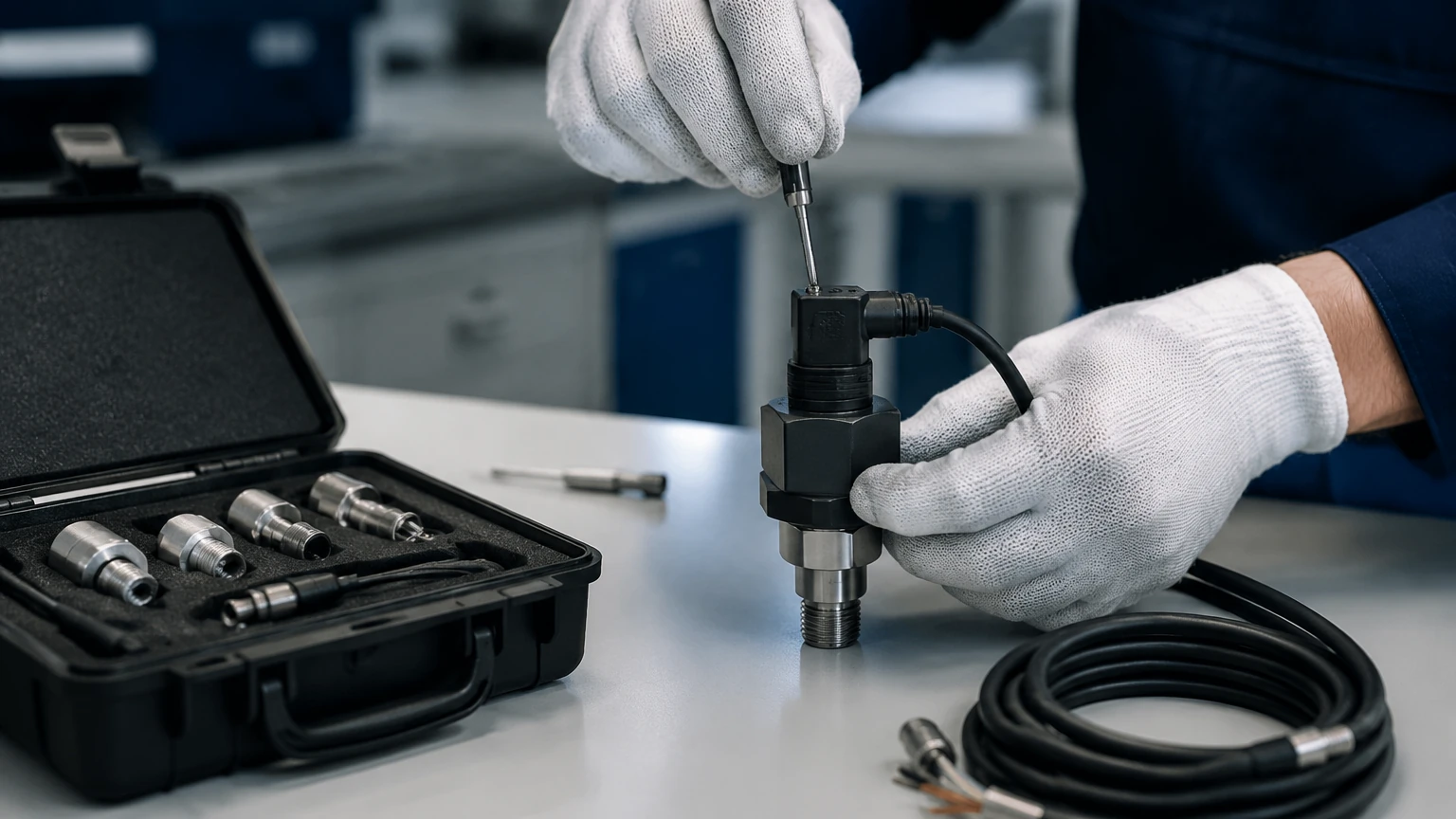
The following procedure outlines a standard 5-point calibration check, which is the industry norm for verifying linearity and hysteresis.
1. Preparation and Safety
Ensure the sensor is isolated from the process. Bleed any residual pressure and disconnect the wiring if performing a bench calibration. Clean the process connection to ensure no debris interferes with the pressure port.
2. Zero Adjustment (The Lower Range Value)
With the sensor open to the atmosphere (0 bar gauge), check the output signal. For a 4-20 mA transmitter, the output should be exactly 4.000 mA. If the reading is off, perform a "Zero Trim" using a HART communicator or the local adjustment buttons. This aligns the sensor's internal software with the physical state of zero pressure.
3. The 5-Point Calibration Check
Apply pressure in increments to verify the sensor's performance across its entire calibrated range (URL – Upper Range Limit).
* 0% (LRV): Apply 0 bar, record mA output.
* 25%: Apply 25% of the span, record mA output (should be 8 mA).
* 50%: Apply 50% of the span, record mA output (should be 12 mA).
* 75%: Apply 75% of the span, record mA output (should be 16 mA).
* 100% (URV): Apply 100% of the span, record mA output (should be 20 mA).
4. Span Adjustment
If the error at the 100% mark exceeds the manufacturer's specified accuracy (e.g., ±0.1% of span), a "Span Trim" is required. Using the pressure source, hold the pressure exactly at the URV and use the communicator to tell the transmitter that the current pressure represents the 100% point.
5. Hysteresis Check
After reaching 100%, decrease the pressure back through the same increments (75%, 50%, 25%, 0%). If the readings during the descending phase differ significantly from the ascending phase, the sensor may have mechanical fatigue or a damaged diaphragm.
Selection Table for Industrial Pressure Sensors
Choosing the right sensor involves balancing accuracy requirements with the frequency of calibration. The following table provides a comparison of common sensor types found on the Main Page of Welk’s technical catalog.
| Sensor Technology | Typical Accuracy | Long-term Stability | Calibration Interval | Best Application |
| :— | :— | :— | :— | :— |
| Piezoresistive Silicon | 0.075% – 0.1% FS | <0.1% / Year | 12 – 24 Months | Clean liquids, water treatment |
| Ceramic Capacitive | 0.1% – 0.2% FS | <0.15% / Year | 18 – 36 Months | Corrosive chemicals, slurries |
| Metal Diaphragm | 0.2% – 0.5% FS | <0.2% / Year | 12 Months | High temperature, steam lines |
| Submersible Hydrostatic | 0.1% – 0.5% FS | <0.2% / Year | 6 – 12 Months | Deep wells, reservoirs |
Installation and Maintenance Considerations
The physical installation of a pressure sensor can impact its calibration. Engineers should consider the following to minimize errors:
* Mounting Position: Sensors calibrated in a vertical position may show a slight zero shift if mounted horizontally due to the weight of the internal fill fluid (oil) pressing against the diaphragm. Always zero the sensor in its final mounting orientation.
* Impulse Lines: For gas measurement, ensure lines slope upward to allow condensate to drain. For liquids, slope downward to prevent air bubbles from being trapped, which can cause erratic pressure readings.
* Temperature Effects: While most modern transmitters have internal temperature compensation, extreme ambient heat can still cause drift. Use heat siphons or cooling towers for high-temperature process fluids.
* Environmental Sealing: Ensure the vent tube (for gauge pressure sensors) is clear and protected by a moisture filter. A blocked vent will cause the sensor to behave like an absolute pressure sensor, leading to errors as atmospheric pressure changes.
Limitations and Common Risks in Pressure Calibration
While the process to calibrate pressure sensor units is straightforward, several risks can compromise the results:
* Overpressure Damage: Applying pressure beyond the sensor's proof pressure during calibration can permanently deform the diaphragm, leading to non-linear errors that cannot be calibrated out.
* Contamination: Using a hydraulic pump with oil to calibrate a sensor intended for oxygen service or food processing is a critical safety and hygiene risk. Always use the appropriate pressure medium (air, nitrogen, or deionized water).
* Reference Uncertainty: If the reference gauge has not been calibrated recently, the entire process is invalid. Always verify the calibration certificates of your test equipment.
* Ambient Temperature Fluctuations: Performing a high-precision calibration in an outdoor environment with shifting temperatures can introduce errors. Ideally, bench calibration should be performed in a climate-controlled lab at approximately 20°C (68°F).
Frequently Asked Questions (FAQs)
Q: How often should I calibrate my pressure sensor?
A: For most industrial applications, an annual calibration is standard. However, if the sensor is used in a safety-critical system (SIL rated) or a highly corrosive environment, a 6-month interval may be required. Consult the manufacturer's long-term stability specifications for guidance.
Q: What is the difference between a "Zero Trim" and a "Re-ranging"?
A: A Zero Trim corrects for a shift in the sensor's baseline without changing the measurement scale. Re-ranging changes the 4mA and 20mA points (e.g., changing a 0-10 bar scale to 0-5 bar). Re-ranging does not necessarily improve accuracy; it only changes the output scaling.
Q: Can I calibrate a pressure sensor while it is still in the pipe?
A: Yes, this is known as field calibration. It requires a 3-way manifold or a block-and-bleed valve to isolate the sensor from the process while allowing a portable pressure pump to be connected to the test port.
Q: Why does my sensor reading change when I tighten the process connection?
A: This is known as mounting torque effect. Tightening the sensor into a port can cause minor stresses on the housing that transfer to the sensing element. This is why it is critical to perform a zero check *after* the sensor is installed.
Conclusion
Accurate pressure measurement is a cornerstone of industrial process engineering. By following a structured approach to calibrate pressure sensor equipment, facilities can ensure long-term reliability and minimize the risk of process deviations. Whether you are managing water distribution or complex chemical reactors, the selection of high-quality instrumentation and a commitment to regular maintenance are key.
For engineers seeking reliable measurement hardware and detailed technical support, visiting the Main Page provides access to a wide range of radar, ultrasonic, and hydrostatic level solutions designed for the most demanding industrial environments. Proper calibration, combined with robust instrument selection, ensures that your data remains a dependable asset for operational decision-making.