Vega Group
Vega Group
In the landscape of industrial automation and process control, the Vega Group stands as a definitive benchmark for level and pressure measurement technology. Based in Schiltach, Germany, this organization has spent decades refining the methods by which industries measure liquids and bulk solids. For process engineers and procurement specialists, understanding the technological contributions and product standards established by the Vega Group is essential when evaluating instrumentation for complex industrial environments. This guide examines the core measurement principles, selection criteria, and engineering considerations that define modern level measurement, providing a practical reference for those navigating the Main Page of industrial sensor technology.
The Evolution of Level Measurement Technology
Level measurement has transitioned from simple mechanical floats to sophisticated electronic sensors capable of measuring through foam, dust, and high-pressure vapors. The Vega Group played a pivotal role in this evolution, particularly with the introduction of the first industrial radar level sensor in the 1990s. Today, the industry relies on a variety of technologies, each suited to specific physical properties of the media and the environment of the vessel.
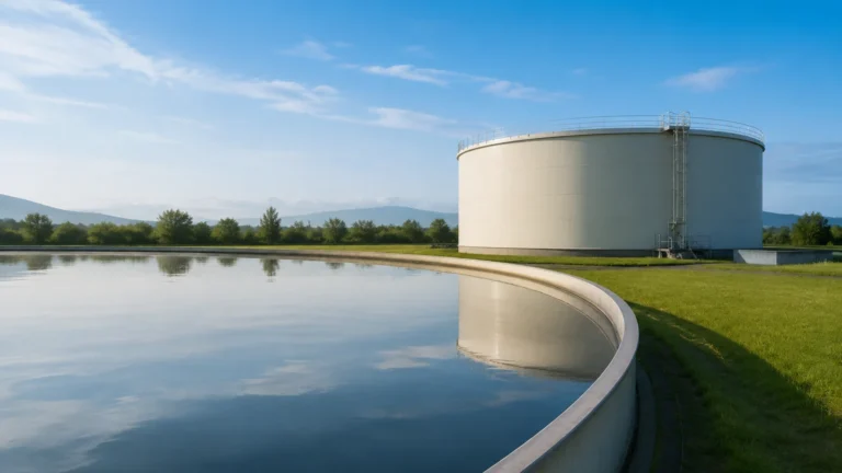
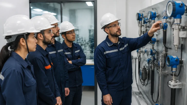
Modern instrumentation must provide high reliability and accuracy to ensure plant safety and efficiency. Whether it is a chemical reactor, a water treatment tank, or a grain silo, the choice of sensor dictates the stability of the entire control loop. Understanding the physics behind these sensors is the first step in successful implementation.
Core Measurement Principles
Before selecting a device, it is critical to understand the underlying measurement principles. Most modern industrial level sensors fall into four primary categories: Radar, Guided Wave Radar, Ultrasonic, and Hydrostatic.
Radar Level Measurement (Non-Contact)
Non-contact radar sensors emit high-frequency microwave signals, typically in the 26 GHz or 80 GHz range. These signals reflect off the surface of the medium and return to the sensor. The distance is calculated based on the time-of-flight (ToF) principle.
* 80 GHz Technology: This higher frequency allows for a much narrower beam angle (as small as 3 degrees), which is vital for avoiding internal obstructions like agitators or heating coils. It also provides better performance in vessels with significant buildup on the antenna.
* 26 GHz Technology: Often used for larger vessels where a slightly wider beam is acceptable and cost-effectiveness is a priority.
Guided Wave Radar (GWR)
Guided Wave Radar uses Time Domain Reflectometry (TDR). Instead of broadcasting through the air, the microwave pulse is guided along a probe (cable or rod). When the pulse reaches the product surface, the change in the dielectric constant causes a reflection. GWR is exceptionally stable because the signal is contained, making it immune to dust, steam, and surface turbulence.
Ultrasonic Level Sensors
Ultrasonic sensors emit acoustic pulses. The time taken for the sound wave to bounce back from the surface determines the level. While cost-effective, ultrasonic sensors are sensitive to air temperature changes, heavy dust, and vacuum conditions, as sound requires a medium (air) to travel through.
Hydrostatic Pressure
This method measures the pressure exerted by a liquid column. The pressure is directly proportional to the height of the liquid and its density. It is a contact-based method often used in open tanks or vented vessels where liquid density remains relatively constant.
Selection Criteria for Industrial Applications
Choosing the right instrument requires a detailed analysis of the process conditions. The following table provides a comparison of the most common technologies used by the Vega Group and other professional manufacturers like Welk.
Technology Selection Matrix
| Feature | Radar (80 GHz) | Guided Wave Radar | Ultrasonic | Hydrostatic |
| :— | :— | :— | :— | :— |
| Media Type | Liquids & Solids | Liquids & Solids | Liquids & Solids | Liquids Only |
| Accuracy | ±1 mm | ±2 mm | ±0.2% of range | ±0.1% of span |
| Max Range | Up to 120 m | Up to 75 m | Up to 15 m | Up to 250 m |
| Pressure | Up to 160 bar | Up to 400 bar | Atmospheric | Up to 40 bar |
| Temperature | -196 to +450 °C | -196 to +450 °C | -40 to +80 °C | -40 to +100 °C |
| Effect of Dust | None | None | High | None |
| Effect of Foam | Minimal | Minimal | Significant | None |
Key Evaluation Factors
1. Dielectric Constant (dk): Radar and GWR depend on the reflectivity of the medium. Materials with low dk (like oils or plastic pellets) reflect less energy than water-based liquids. If the dk is below 1.4, a guided wave radar or a specialized high-sensitivity non-contact radar is required.
2. Vessel Geometry: Narrow tanks or those with internal structures require the precision of 80 GHz radar to prevent "false echoes" from the tank walls or pipes.
3. Process Atmosphere: If the tank contains heavy steam, vapors, or a vacuum, ultrasonic sensors will likely fail. Radar is generally unaffected by these conditions.
Installation Best Practices and Engineering Considerations
Correct installation is as important as selecting the right technology. Even the highest quality sensor from the Vega Group will provide inaccurate data if mounted incorrectly.
Mounting Position
* Avoid the Center: In cylindrical tanks, do not mount the sensor in the exact center, as this can lead to multiple reflections that interfere with the primary signal.
* Nozzle Height: The sensor antenna should ideally extend slightly past the mounting nozzle to prevent interference from the nozzle edges. If the nozzle is long, an 80 GHz sensor is preferred due to its narrow beam.
* Inflow Path: Never install a sensor directly above the filling stream. The turbulence and the falling material will cause signal noise and erratic readings.
Dead Zones (Blocking Distance)
Every sensor has a "dead zone" or "blocking distance" near the antenna where measurement is not possible. For ultrasonic sensors, this can be 20 cm to 80 cm. For high-frequency radar, this zone is significantly smaller, often only a few centimeters, allowing for better utilization of the full tank volume.
Power and Communication
Most industrial level meters utilize a 2-wire 4-20mA loop with HART protocol. This allows for digital communication over the existing analog wiring, enabling remote configuration and diagnostics. For integration into modern PLC/SCADA systems, Modbus RTU or Profibus PA options are also common.

Limitations and Common Risk Factors
While modern instrumentation is robust, certain factors can compromise performance:
* Condensation and Buildup: In high-humidity applications, water droplets can form on the sensor face. While many radar sensors feature "drip-off" antenna designs, heavy buildup of viscous materials (like bitumen or heavy resins) may eventually require manual cleaning or the use of an air purge system.
* Surface Turbulence: Rapidly boiling liquids or heavy agitation can scatter radar signals. In these cases, using a bypass pipe or a stilling well can provide a calm surface for accurate measurement.
* Density Fluctuations: For hydrostatic sensors, any change in the liquid's temperature or composition that alters its density will cause a direct error in the level reading. If density is not constant, radar is a superior choice.
Frequently Asked Questions (FAQ)
Q: Can radar sensors measure through plastic tank walls?
A: Yes, non-contact radar can often measure through the tops of plastic or fiberglass tanks, allowing for installation without cutting into the vessel. This is common in chemical storage applications.
Q: What is the difference between a level transmitter and a level switch?
A: A level transmitter provides continuous measurement (e.g., 0-100%), whereas a level switch (like a vibrating fork or float switch) only detects if the liquid has reached a specific point (High or Low alarm).
Q: How often do these sensors need calibration?
A: Most modern solid-state radar and ultrasonic sensors do not "drift" in the traditional sense. However, annual verification is recommended for safety-critical applications or where regulatory compliance is required.
Q: Is 80 GHz always better than 26 GHz?
A: Not necessarily. While 80 GHz offers better focusing, 26 GHz can sometimes be more effective in extremely dusty environments where the longer wavelength can penetrate thick dust clouds more easily.
Conclusion
The standards set by the Vega Group have helped define the reliability we expect from industrial level measurement today. By understanding the physics of radar and ultrasonic waves, and by carefully accounting for process variables like temperature, pressure, and dielectric constants, engineers can select instrumentation that ensures long-term operational success. For those looking to implement these technologies in their own facilities, reviewing the various product options and application supports available on the Main Page is a recommended next step. Whether you are dealing with simple water storage or complex chemical processing, the right level measurement solution is a cornerstone of industrial safety and efficiency.