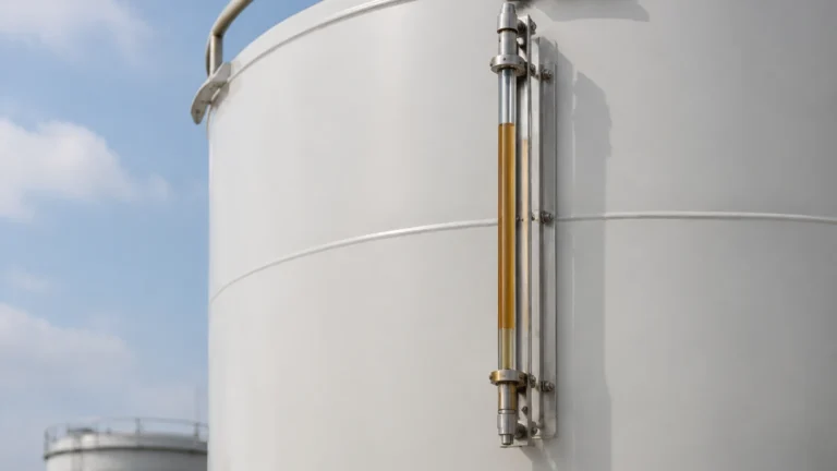
Fuel Gas Knockout Drum
Fuel Gas Knockout Drum
In industrial combustion systems, the purity of fuel gas is paramount to the longevity and efficiency of downstream equipment such as gas turbines, boilers, and flare headers. A fuel gas knockout drum (KO drum), also known as a vapor-liquid separator or scrubber, serves as a critical safety and process vessel designed to remove entrained liquids from a gas stream. This article provides a technical overview of the engineering principles, level measurement requirements, and selection criteria for instrumentation within these vessels.
Understanding the Role of the Fuel Gas Knockout Drum
The primary function of a fuel gas knockout drum is to prevent "slugs" of liquid or fine mists from entering the fuel gas supply line. Liquids in fuel gas can lead to catastrophic consequences, including flame instability, burner damage, turbine blade erosion, and increased emissions. In flare systems, a knockout drum ensures that only vapor is sent to the flare tip, preventing "burning rain," which occurs when ignited liquid is ejected from the flare.
These vessels are typically installed at the battery limits of a facility, immediately upstream of pressure-reducing stations, or before critical combustion units. Because the liquid collected is often a mixture of water, heavy hydrocarbons, and condensed glycols, the vessel must be equipped with reliable level monitoring to manage the drainage process effectively.
Operational Principles of Liquid Separation
The separation of liquid from gas in a fuel gas knockout drum relies on three primary physical mechanisms:
1. Gravity Settling: As the gas enters the larger diameter of the drum, its velocity drops significantly. If the upward velocity of the gas is lower than the settling velocity of the liquid droplets, the droplets fall to the bottom of the vessel.
2. Impingement: Many drums incorporate internal baffles or inlet diverters. When the gas stream hits these surfaces, the heavier liquid droplets lose momentum and coalesce, eventually trickling down to the liquid collection section.
3. Centrifugal Force: In some designs, the gas is introduced tangentially, creating a cyclone effect that throws liquid droplets against the vessel walls.
To enhance efficiency, mist eliminators or "demister pads" (typically made of wire mesh or vanes) are often installed near the gas outlet. These capture microscopic droplets that are too small to settle by gravity alone. For engineers looking to optimize these systems, reviewing the Main Page of instrumentation providers can offer insights into how different sensors interact with these internal components.
Level Measurement Technologies for Knockout Drums
Effective level control is the most critical aspect of fuel gas knockout drum operation. If the liquid level rises too high, the drum loses its separation capacity, leading to carryover. Conversely, if the drum is drained too far, gas can escape into the liquid disposal system (blow-by).
Magnetic Level Gauges (MLG)
This technology utilizes a bypass chamber mounted to the side of the vessel. Inside the chamber, a float containing a high-intensity magnet moves with the liquid level. Outside the chamber, a series of bi-color flaps or a follower indicates the level visually.
* Principle: Buoyancy and magnetic coupling.
* Advantages: No power required for visual indication; high pressure and temperature resilience; clear visibility from a distance.
* Application: Ideal for primary visual monitoring and as a redundant system for electronic transmitters.
Guided Wave Radar (GWR)
GWR transmitters send low-energy microwave pulses down a probe (waveguide). When the pulse hits the liquid surface, the change in dielectric constant causes a reflection back to the transmitter.
* Principle: Time Domain Reflectometry (TDR).
* Advantages: Highly accurate; unaffected by changes in gas pressure, temperature, or density; no moving parts to wear out.
* Application: Preferred for continuous level control and integration into Distributed Control Systems (DCS).
Ultrasonic Level Sensors
These non-contact sensors emit high-frequency sound waves that reflect off the liquid surface.
* Principle: Time-of-flight of sound waves.
* Advantages: Non-contacting, which reduces maintenance in corrosive environments.
* Limitations: Performance can be affected by high pressure or heavy vapors that change the speed of sound in the gas space.
Point Level Switches
Used primarily for High-High (HH) and Low-Low (LL) alarms, these switches provide a discrete signal when liquid reaches a specific point. Tuning fork switches and float switches are the most common types used in fuel gas applications.
Selection Criteria and Technical Specifications
When specifying instrumentation for a fuel gas knockout drum, engineers must evaluate several process variables to ensure long-term reliability.
| Feature | Magnetic Level Gauge | Guided Wave Radar | Ultrasonic Sensor |
| :— | :— | :— | :— |
| Accuracy | ±10 mm (0.4 in) | ±2 mm (0.08 in) | ±0.25% of range |
| Pressure Range | Up to 320 bar | Up to 400 bar | Typically < 3 bar |
| Temp. Range | -196°C to 450°C | -196°C to 450°C | -40°C to 80°C |
| Maintenance | Low (Visual check) | Very Low | Low |
| Output | Visual (Optional 4-20mA) | 4-20mA / HART / Foundation Fieldbus | 4-20mA / HART |
Fluid Characteristics
Fuel gas condensate can be chemically aggressive or contain paraffin/wax. In cold climates, the liquid may thicken. If the condensate is prone to coating, GWR probes with specialized coatings or Magnetic Level Gauges with oversized chambers are recommended.
Safety Integrity Level (SIL)
Because the knockout drum is a safety-critical vessel, the level instruments often contribute to a Safety Instrumented Function (SIF). It is common to see a 2oo3 (two out of three) voting logic for high-level trips to prevent spurious shutdowns while maintaining high safety availability.

Installation Guidelines and Best Practices
Proper installation is as important as technology selection. Incorrectly placed nozzles or poor grounding can lead to signal interference or mechanical failure.
1. Nozzle Placement: Level instrument nozzles should be located away from the inlet stream to avoid turbulence and false readings caused by splashing liquid.
2. Stilling Wells: For internal GWR or ultrasonic installations, a stilling well (a pipe inside the vessel) can help stabilize the liquid surface and provide a stronger signal return.
3. Heat Tracing: In many regions, fuel gas knockout drums require heat tracing and insulation. This prevents the liquid from freezing or heavy hydrocarbons from waxing, which could jam a float-based instrument.
4. Venting and Draining: Bypass chambers for magnetic gauges must include high-point vents and low-point drains to allow for safe maintenance and calibration checks.
Common Operational Risks and Mitigation
* Liquid Carryover: Often caused by undersized vessels or failed level controls. Mitigation involves redundant high-level alarms and regular inspection of demister pads.
* Paraffin Buildup: In heavy fuel gas streams, wax can accumulate on floats or radar probes. Using non-contacting radar or heated MLG chambers can mitigate this risk.
* Foaming: If the fuel gas contains surfactants (e.g., from an upstream glycol dehydrator), foam may form on the liquid surface. GWR is generally better at handling foam than ultrasonic sensors, as the radar pulse can often penetrate the foam to find the true liquid level.
Frequently Asked Questions (FAQ)
Q: How often should the level instruments on a fuel gas knockout drum be calibrated?
A: While modern electronic instruments like GWR are very stable, a functional test (proof test) should be conducted annually or in accordance with the facility's safety management system. Magnetic gauges should be checked for float integrity during plant turnarounds.
Q: Can a single instrument provide both control and safety functions?
A: While technically possible, safety standards like IEC 61511 generally recommend physical separation between the Basic Process Control System (BPCS) and the Safety Instrumented System (SIS). Using two different technologies (e.g., GWR for control and a Tuning Fork for the high-level trip) provides diverse redundancy.
Q: What is the typical size of a fuel gas knockout drum?
A: Sizing depends entirely on the gas flow rate and the required liquid holdup time (typically 10 to 30 minutes). Small units may be only 0.5 meters in diameter, while large flare KO drums can exceed 4 meters in diameter.
Pre-Procurement Checklist for Engineering Teams
Before finalizing the specification for a fuel gas knockout drum project, ensure the following data points are confirmed:
* Maximum and Minimum Operating Pressure: Ensure the instrument housing and flanges meet the vessel's design pressure.
* Fluid Dielectric Constant: Required for accurate GWR configuration.
* Specific Gravity of Condensate: Critical for sizing Magnetic Level Gauge floats to ensure they remain buoyant.
* Hazardous Area Classification: Most fuel gas applications require ATEX, IECEx, or UL/CSA explosion-proof certifications.
* Mounting Requirements: Confirm flange sizes (e.g., DN50, 2" ANSI) and center-to-center distances for side-mounted instruments.
For comprehensive technical support and a review of instrument options tailored to these specifications, engineers are encouraged to visit the Main Page for detailed product documentation and application engineering assistance.