Real Time Cip Sensors
Real Time Cip Sensors
Clean-in-Place (CIP) systems are fundamental to modern industrial processing, particularly in the food and beverage, pharmaceutical, and chemical sectors. These systems allow for the internal surfaces of pipes, vessels, and equipment to be cleaned without disassembly. To ensure these processes are both effective and efficient, the integration of real time cip sensors is essential. These instruments provide the continuous data necessary to automate cleaning cycles, reduce chemical waste, and verify that hygiene standards are met.
In a B2B context, selecting the right instrumentation requires an understanding of how different physical principles—such as electromagnetism, acoustics, and pressure—interact with cleaning agents and process environments. This guide explores the engineering principles, selection criteria, and practical application of sensors used in real-time CIP monitoring.
Measurement Principles in CIP Environments
Real-time monitoring in a CIP cycle typically involves tracking four primary variables: concentration, temperature, flow, and level. Each utilizes specific physical principles to provide actionable data.
Conductivity and Concentration
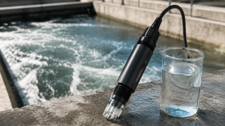
Conductivity sensors are the primary tool for identifying the interface between different fluids (e.g., water vs. caustic soda). The principle is based on the ability of a liquid to conduct an electrical current. Cleaning agents like sodium hydroxide or nitric acid increase the ion concentration in the solution, significantly raising conductivity. By monitoring this in real time, the system can determine exactly when the chemical concentration has reached the required threshold for effective sanitation.
Level Measurement Principles
Monitoring the level of cleaning tanks and process vessels is critical to prevent pump cavitation or tank overfills. Several technologies are employed:
* Radar (Time-of-Flight): High-frequency microwave pulses are emitted toward the liquid surface. The time taken for the pulse to reflect back is measured. Because radar is independent of density and temperature, it is highly reliable in the varying conditions of a CIP cycle.
* Ultrasonic: Similar to radar but uses sound waves. While cost-effective, ultrasonic sensors can be affected by the heavy steam often present during hot wash cycles.
* Hydrostatic Pressure: This method measures the pressure exerted by the liquid column. It is a direct measurement of mass, provided the density of the cleaning fluid is known.
Flow and Velocity
CIP effectiveness relies on mechanical action, often referred to as "scrubbing." This requires maintaining a specific flow velocity (typically 1.5 to 2.1 meters per second) to ensure turbulent flow in the piping. Electromagnetic flowmeters are commonly used here because they offer no obstruction to the flow and are highly resistant to aggressive chemicals.
Key Types of Real Time Cip Sensors
For engineers designing or maintaining a CIP system, the choice of sensor depends on the specific stage of the cleaning process and the physical layout of the plant. For comprehensive technical specifications on industrial instrumentation, engineers often consult the Main Page of specialized manufacturers to compare performance data.
1. Radar Level Transmitters
In vessels where spray balls are active, the environment is turbulent and filled with mist. 80 GHz high-frequency radar sensors are preferred because their narrow beam angle avoids internal obstructions like agitators or spray headers. They provide a continuous level reading that allows the control system to manage the volume of cleaning fluids precisely.
2. Inductive Conductivity Sensors
Unlike traditional contact-based conductivity sensors, inductive (or toroidal) sensors use two coils encased in a plastic body (often PEEK or PFA). This design eliminates the risk of electrode polarization and coating, which are common issues when using heavy caustic or acidic solutions. They are the "eyes" of the CIP system, identifying the transition from rinse water to cleaning solution.
3. Hydrostatic Level Sensors
For balance tanks or recovery tanks, hydrostatic sensors provide a robust solution. These sensors must feature a flush-mount diaphragm to prevent the buildup of bacteria or process media in "dead legs." They are particularly useful when the tank headspace is pressurized or under vacuum, conditions that might complicate ultrasonic measurements.
4. Point Level Switches
While continuous measurement is ideal, point level switches (such as vibrating forks) serve as critical safety backups. They detect high-level or low-level states to prevent dry-running of pumps or environmental spills during the high-volume rinse phases.
Selection Criteria for CIP Instrumentation
Choosing real time cip sensors involves more than just selecting a measurement range. The harsh nature of the cleaning process dictates specific hardware requirements.
| Feature | Requirement | Reason |
| :— | :— | :— |
| Material Compatibility | 316L Stainless Steel / PEEK / PTFE | Resistance to nitric acid, phosphoric acid, and sodium hydroxide. |
| Hygienic Design | EHEDG or 3-A Certification | Ensures the sensor itself does not harbor microbial growth. |
| Surface Finish | Ra < 0.8 μm | Smooth surfaces allow for easier cleaning and prevent biofilm attachment. |
| Temperature Rating | Up to 140°C (284°F) | Must withstand SIP (Sterilization-in-Place) steam cycles. |
| Ingress Protection | IP69K | Protection against high-pressure, high-temperature washdowns. |
Installation Considerations and Best Practices
Proper installation is as important as sensor selection. Even the best sensor will fail or provide inaccurate data if installed incorrectly in a CIP loop.
1. Avoid Dead Legs: Sensors should be installed in a way that the cleaning fluid can reach the sensing element directly. A common rule is the "2D" rule, where the length of the mounting tee should not exceed twice its diameter.
2. Mounting Orientation: Flow and conductivity sensors should be installed in vertical pipe sections with upward flow. This ensures the pipe is always full, preventing air pockets that cause measurement errors.
3. Thermal Shock Resistance: During CIP, a sensor might be exposed to a 5°C rinse immediately following an 85°C caustic wash. Ensure the sensor electronics and seals are rated for rapid thermal cycling to prevent diaphragm fatigue or seal failure.
4. Spray Ball Interference: Level sensors, particularly radar and ultrasonic types, should be positioned away from the direct path of CIP spray balls to avoid signal noise or physical damage to the sensor face.

Limitations and Operational Challenges
While real-time sensors significantly improve CIP efficiency, they are not without limitations:
* Foaming: High-protein processes (like dairy) can generate significant foam during the cleaning cycle. Foam can absorb ultrasonic signals and cause "false high" readings in some capacitance-based sensors. Radar is generally more resistant but may still require specific frequency tuning.
* Scaling: Over time, minerals from hard water or process residues can build up on sensor faces. While inductive conductivity sensors are resistant, pressure diaphragms and optical sensors may require periodic manual inspection.
* Signal Integration: In older plants, integrating real-time data into a legacy PLC can be challenging. Modern sensors often utilize IO-Link, which provides not only the primary measurement but also diagnostic data (e.g., internal temperature, signal quality) that helps predict when a sensor might need maintenance.
Frequently Asked Questions (FAQs)
Q: Why is real-time monitoring better than manual sampling?
A: Manual sampling is slow and only provides a snapshot in time. Real-time monitoring allows for "interface detection," meaning the system switches valves the instant the fluid changes, saving thousands of liters of water and chemicals annually.
Q: Can I use the same level sensor for both production and CIP?
A: Yes, provided the sensor is rated for the maximum temperature of the CIP/SIP cycle and is made of materials compatible with both the product and the cleaning agents.
Q: What is the most common cause of sensor failure in CIP?
A: Moisture ingress due to improper sealing and thermal shock are the leading causes. Using sensors with an IP69K rating and potted electronics can mitigate these risks.
Q: How often should CIP sensors be calibrated?
A: This depends on local regulations (e.g., FDA or ISO standards), but typically conductivity and temperature sensors are calibrated annually or semi-annually to ensure the cleaning cycle remains within validated parameters.
Conclusion
The implementation of real time cip sensors is a strategic investment for any industrial facility aiming to optimize its cleaning processes. By understanding the underlying measurement principles—from the electromagnetic properties used in conductivity sensing to the time-of-flight calculations in radar level meters—engineers can design systems that are both compliant with hygiene standards and economically efficient. When selecting equipment, prioritizing hygienic design, material compatibility, and robust data integration will ensure long-term reliability in the most demanding process environments.