Radar Level Sensor Calibration
Radar Level Sensor Calibration: A Technical Engineering Guide
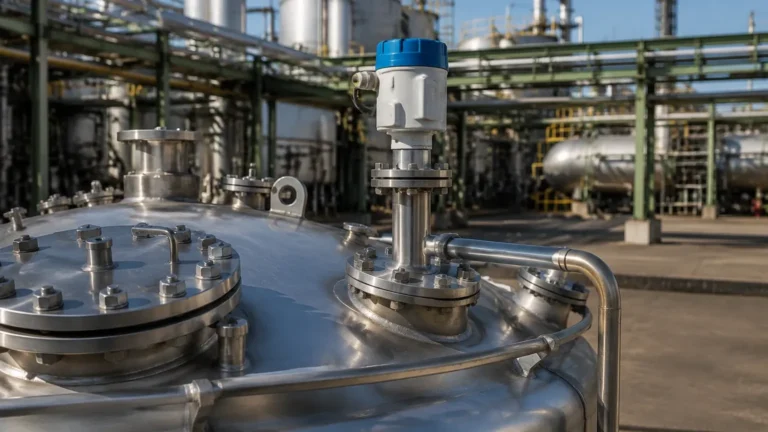
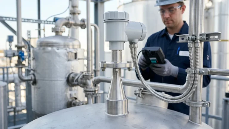
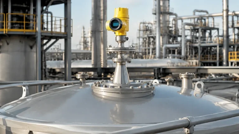
In the landscape of industrial process automation, achieving precise inventory management and process control depends heavily on the accuracy of level instrumentation. Among the various technologies available, Radar Level Meters have emerged as the industry standard for non-contact measurement in challenging environments. However, the reliability of these instruments is not solely a product of their hardware; it is equally dependent on precise radar level sensor calibration and correct installation.
This guide explores the technical principles of radar technology, the systematic approach to calibration, and the engineering considerations necessary to ensure long-term operational accuracy in B2B industrial applications.
1. Understanding Radar Measurement Principles
Before addressing the specifics of calibration, engineers must understand how radar sensors interact with the process medium. Radar level measurement is based on the Time of Flight (ToF) principle. The sensor emits electromagnetic pulses or a continuous wave that travels at the speed of light. When these waves encounter a medium with a different dielectric constant than the air or vapor space, a portion of the energy is reflected back to the sensor.
Pulse Radar vs. FMCW
There are two primary methods used in industrial radar level measurement:
* Pulse Radar: The instrument emits a microwave pulse and measures the time it takes for the pulse to travel to the surface and back. This is effective for many standard applications but can struggle with low-dielectric materials or high-turbulence environments.
* Frequency Modulated Continuous Wave (FMCW): This technology emits a continuous signal with a constantly changing frequency. The distance is calculated by comparing the frequency difference between the transmitted and received signals. FMCW, particularly at higher frequencies like 80 GHz, offers superior resolution and signal-to-noise ratios, making it the preferred choice for high-precision industrial requirements.
2. The Core of Radar Level Sensor Calibration
In the context of radar technology, "calibration" often refers to the digital configuration of the transmitter to match the physical geometry of the vessel. Unlike hydrostatic transmitters that require physical pressure for zeroing, radar level sensor calibration is primarily a software-driven process that defines the measurement boundaries.
Key Calibration Parameters
To calibrate a radar sensor effectively, the following parameters must be defined within the instrument's microprocessor:
1. Reference Point: Usually the bottom of the sensor flange or the threaded connection. All measurements are calculated from this datum.
2. Empty Distance (Zero Point): The linear distance from the reference point to the bottom of the tank (0% level). If the sensor is calibrated incorrectly here, it may report a residual level even when the tank is empty.
3. Full Distance (Span): The distance from the empty point to the maximum desired fill level (100% level). Note that the 100% mark must remain below the sensor's "dead zone" or "blocking distance."
4. Dielectric Constant (εr): This is a critical factor. The dielectric constant of the material determines the strength of the reflected signal. For materials with low εr (like oils or liquefied gases), the sensor sensitivity must be increased.
False Echo Suppression (Mapping)
One of the most vital steps in calibration is "echo mapping." Industrial tanks often contain internal obstructions such as agitators, heating coils, or ladders. These objects reflect radar signals, potentially creating "ghost" levels. During the commissioning phase, engineers perform a mapping scan of the empty or partially empty tank. The software records these static reflections and programs the sensor to ignore them, focusing only on the dynamic return signal from the product surface.
3. Technical Selection Criteria
Choosing the right instrument is a prerequisite for successful calibration. The frequency of the radar determines the beam angle and the ability to penetrate dust or steam.
| Feature | 26 GHz Radar | 80 GHz Radar |
| :— | :— | :— |
| Beam Angle | Wider (approx. 10°–20°) | Narrower (approx. 3°–8°) |
| Application | Large tanks, simple geometries | Tall/narrow silos, tanks with obstructions |
| Accuracy | ±3 mm to ±5 mm | ±1 mm |
| Dust/Steam Penetration | Good | Excellent |
| Nozzle Compatibility | Requires larger nozzles | Works well with small/long nozzles |
When selecting Radar Level Meters, buyers should confirm the material's dielectric constant and the presence of foam, as these factors dictate whether a standard non-contact radar or a Guided Wave Radar (GWR) is required.
4. Installation Constraints and Best Practices
Calibration cannot compensate for poor installation. To ensure the radar signal remains clean and accurate, follow these engineering guidelines:
Positioning and Clearance
* The 1/6 Rule: Generally, the sensor should be installed at a distance of 1/6 of the tank diameter from the tank wall. Installing too close to the wall causes interference from side-lobe reflections; installing in the center can cause multiple-path interference in domed-roof tanks.
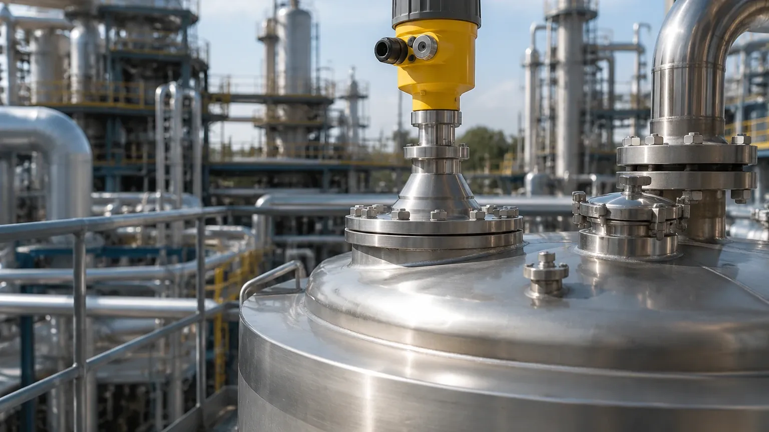
* Nozzle Geometry: The sensor antenna should ideally extend slightly beyond the bottom of the mounting nozzle. If the nozzle is too long or narrow, it creates internal reflections that can mask the true level signal.
* Obstruction Avoidance: Ensure the signal path is clear of inflow streams. If the product falls through the radar beam, the sensor may provide erratic readings due to the turbulence and the reflection from the falling stream.
Environmental Protection
For outdoor installations or processes with high temperature fluctuations, sunshades or thermal insulators should be used. While radar is largely unaffected by vacuum or pressure, extreme temperatures can affect the electronics' lifespan and the integrity of the antenna seals.
5. Application Risks and Limitations
While highly versatile, radar technology faces specific physical limitations that engineers must account for during the radar level sensor calibration phase:
1. Heavy Foam: Dense, thick foam can absorb the radar signal entirely, leading to a "Loss of Echo" (LOE) error. In such cases, Guided Wave Radar or ultrasonic sensors may be more appropriate, depending on the foam density.
2. Turbulence and Agitation: A highly turbulent surface scatters the radar signal. While software filters (damping) can smooth out the reading, extreme turbulence may require a stilling well or bypass chamber to provide a calm surface for measurement.
3. Low Dielectric Materials: If the medium has a dielectric constant below 1.4, the reflection may be too weak for standard non-contact radar. Specialized high-sensitivity units or GWR units are necessary for these applications.
6. Maintenance and Troubleshooting FAQ
Q: How often should a radar level sensor be recalibrated?
A: Unlike mechanical systems, radar sensors do not suffer from "drift" in the traditional sense. Recalibration is usually only necessary if the tank geometry changes, the medium is swapped for one with a significantly different dielectric constant, or if the sensor is moved to a different vessel.
Q: Why does my sensor show a full tank when it is actually empty?
A: This is often caused by "ringing" or a strong reflection from the mounting nozzle. Ensure the antenna is clean and perform a new false echo suppression map to mask the nozzle reflection.
Q: Can radar measure through a plastic tank lid?
A: Yes. Microwaves can penetrate non-conductive materials like plastic, GRP, or glass. This allows for "tank-side" measurement without cutting a hole in the vessel, provided the material does not contain carbon or metallic reinforcements.
7. Conclusion for International Buyers
For procurement professionals and plant engineers, the successful implementation of Radar Level Meters requires a holistic view of the process. Accuracy is not just a line item on a datasheet; it is the result of matching the correct frequency to the application, adhering to strict installation geometries, and performing a thorough radar level sensor calibration including echo mapping.
When sourcing equipment, always confirm the following with your supplier:
* The minimum dielectric constant the sensor can detect.
* The required nozzle height and diameter for the specific antenna type.
* Whether the software supports field-based false echo suppression.
By following these technical boundaries, industrial facilities can ensure reliable, maintenance-free level measurement that supports both safety and operational efficiency.