Radar Level Rosemount
Radar Level Rosemount: An Engineering Guide to Selection and Application
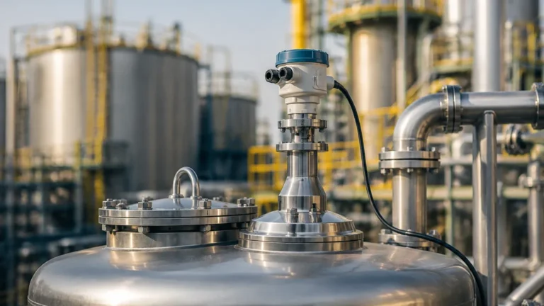
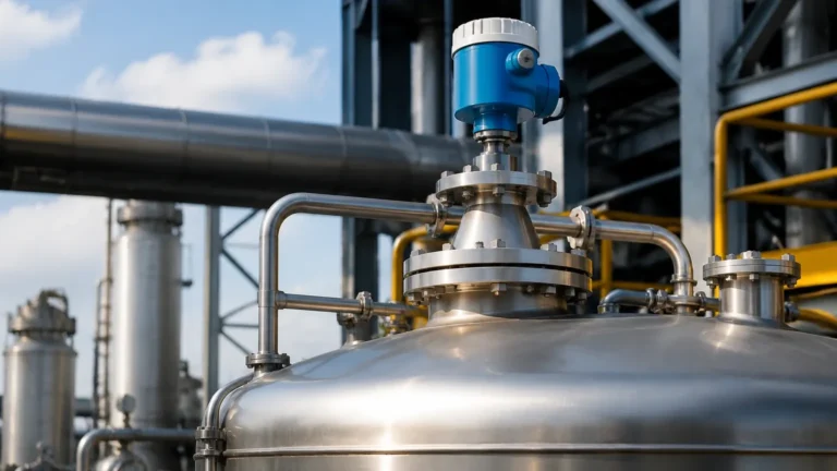
In the landscape of industrial process automation, precise level measurement is a cornerstone of safety, efficiency, and inventory management. Among the various technologies available, non-contacting radar has emerged as a preferred solution for challenging environments. Within this sector, the term radar level rosemount often refers to the industry-standard instrumentation developed by Emerson, known for its reliability in high-stakes applications like oil and gas, chemical processing, and power generation.
Understanding the engineering principles behind these instruments, as well as the broader category of Radar Level Meters, is essential for engineers and procurement specialists tasked with optimizing tank monitoring systems. This guide explores the technical foundations, selection criteria, and installation requirements for radar level measurement.
1. Measurement Principles of Radar Technology
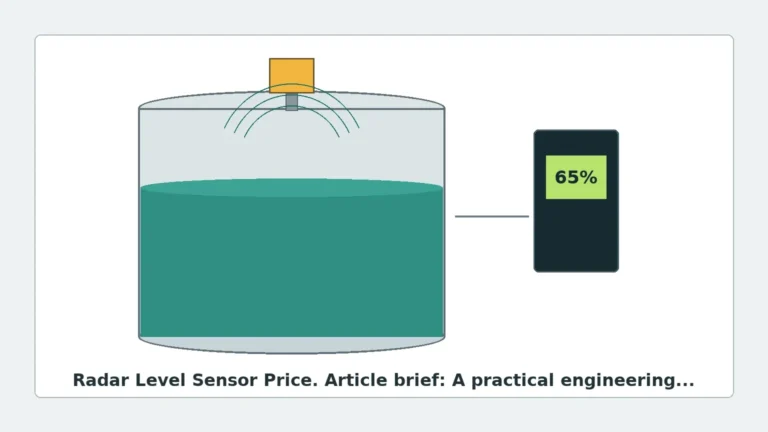
Radar level measurement operates on the principle of reflecting electromagnetic waves off a product surface. Unlike ultrasonic sensors, which use sound waves and are susceptible to air temperature and pressure changes, radar waves travel at the speed of light and are largely unaffected by the vapor space composition.
1.1 Pulse Radar (Time-of-Flight)
Traditional radar level meters often utilize Pulse Radar technology. The transmitter emits a short microwave pulse toward the medium. The signal reflects off the surface and returns to the sensor. The instrument measures the "Time-of-Flight" (ToF) and calculates the distance based on the constant speed of light. While effective for many applications, Pulse Radar can struggle with low-reflectivity surfaces or high-turbulence environments where the signal-to-noise ratio is low.
1.2 Frequency Modulated Continuous Wave (FMCW)
Modern high-performance instruments, including many in the radar level rosemount portfolio (such as the Rosemount 5408), utilize FMCW technology. Instead of a single pulse, the transmitter sends a continuous signal with a constantly changing frequency. The difference between the frequency of the transmitted signal and the reflected signal is proportional to the distance. FMCW provides a much higher resolution and better signal processing capabilities, allowing the meter to distinguish the true level from false reflections caused by internal tank structures.
2. Technical Comparison: Radar Types and Specifications
When selecting between different radar technologies, engineers must evaluate the dielectric constant ($ε_r$) of the medium, the vessel geometry, and the required accuracy. The following table provides a technical comparison of common radar configurations used in industrial settings.
| Feature | Non-Contacting Radar (26GHz) | Non-Contacting Radar (80GHz) | Guided Wave Radar (GWR) |
| :— | :— | :— | :— |
| Measurement Range | Up to 30m (98 ft) | Up to 120m (393 ft) | Up to 75m (246 ft) |
| Beam Angle | 8° to 20° | 3° to 6° | N/A (Signal follows probe) |
| Accuracy | ±3mm to ±5mm | ±1mm to ±2mm | ±2mm to ±5mm |
| Dielectric Constant | ε_r ≥ 1.6 | ε_r ≥ 1.2 | ε_r ≥ 1.4 |
| Typical Applications | Large tanks, simple liquids | Narrow vessels, solids, high precision | Small tanks, foaming liquids, interface |
| Process Temp/Pressure | High | Moderate to High | Extreme (up to 400°C/400 bar) |
3. The Significance of Frequency in Selection
The frequency of the radar signal dictates the beam angle and the instrument's ability to handle obstacles.
* Low Frequency (6GHz – 10GHz): These are less affected by foam, dust, and vapor. They are often used in heavy industrial applications where the surface might be turbulent or covered in a layer of light foam.
* High Frequency (24GHz – 26GHz): This is the standard for most industrial Radar Level Meters. It offers a good balance between antenna size and beam focus.
* Ultra-High Frequency (78GHz – 80GHz): This frequency allows for very small antennas and extremely narrow beam angles. This is critical when installing a sensor in a tank with many internal obstructions (pipes, agitators, or ladders) or when measuring through narrow nozzles.
4. Engineering Constraints: Dielectric Constant and Reflectivity
The dielectric constant ($ε_r$) of the material is the most critical factor in radar level measurement. It determines how much energy is reflected back to the sensor.
* High Dielectric Materials (ε_r > 10): Water-based liquids and acids reflect signals strongly, making them easy to measure even with turbulence.
* Low Dielectric Materials (ε_r < 2): Hydrocarbons, oils, and some solids reflect very little energy. In these cases, a radar level rosemount device with high sensitivity or a Guided Wave Radar (GWR) probe may be necessary to ensure a reliable return signal.
If the dielectric constant is too low, the radar signal may pass through the product and reflect off the bottom of the tank, leading to an incorrect reading. Advanced signal processing software can often compensate for this by using "Bottom Projection" algorithms.
5. Installation Best Practices and Geometric Considerations
Proper installation is the difference between a high-performing system and one plagued by false echoes. Engineers should adhere to the following guidelines:
5.1 Nozzle Dimensions
The nozzle height and diameter must be considered. If the nozzle is too long or narrow, the radar signal may reflect off the internal walls of the nozzle before even entering the tank. For 80GHz radars, this is less of an issue due to the narrow beam, but for 26GHz units, the nozzle should ideally be as short as possible.
5.2 Distance from Tank Walls
Radar sensors should not be mounted too close to the tank wall. A general rule of thumb is to maintain a distance of at least 1/6th of the tank diameter from the wall. This prevents the beam from interacting with the wall surface, which could cause signal attenuation or interference.
5.3 Avoiding Obstructions
Internal structures like heating coils, agitators, and support beams are common sources of "false echoes." While modern software can "map" these obstructions and ignore them, it is best practice to install the meter in a location with a clear line of sight to the product surface. If an agitator is present, the instrument should be configured to filter out the intermittent signals caused by the moving blades.
5.4 Mounting Location
* Avoid the Center: In cylindrical tanks with domed tops, mounting the radar in the exact center can lead to multiple reflections that confuse the sensor.
* Avoid the Inlet: Do not mount the sensor directly above the fill stream, as the falling liquid or solid will interfere with the radar signal.

6. Challenges in Radar Level Measurement
Despite its versatility, radar technology faces specific industrial challenges that require careful engineering workarounds.
6.1 Foam Management
Heavy, dense foam can absorb radar signals, leading to a loss of signal. While low-frequency radars handle light foam better, extremely thick foam may require the use of Guided Wave Radar, where the signal is contained within a probe, or a different technology altogether, such as a magnetic level gauge.
6.2 Vapor and Condensation
While radar is generally immune to vapor, extreme condensation on the antenna can cause signal scattering. Many radar level rosemount models feature PTFE-faced antennas or "drip-off" lens designs that prevent droplets from accumulating on the active surface.
6.3 High-Pressure/High-Temperature Environments
In steam drum or reactor applications, the mechanical seal of the radar antenna is a critical failure point. Specialized ceramic seals and cooling extensions are often required to protect the electronics from process temperatures exceeding 250°C (482°F).
7. Maintenance and Diagnostics
One of the primary advantages of high-end radar systems is their onboard diagnostic capability. Modern transmitters provide real-time data on signal strength and "Signal-to-Noise Ratio" (SNR).
* Signal Quality Metrics: If the signal strength drops over time, it may indicate buildup on the antenna or a change in the product's dielectric properties.
* Remote Verification: Many industrial units allow for remote proof-testing, which is essential for Safety Instrumented Systems (SIS) with SIL 2 or SIL 3 ratings. This allows operators to verify the instrument's functionality without removing it from the process.
8. Frequently Asked Questions (FAQ)
Q: Can radar measure the interface between two liquids?
A: Yes, typically using Guided Wave Radar. The signal reflects off the top layer (low dielectric) and a portion of the signal continues to reflect off the interface of the lower layer (high dielectric, such as water under oil).
Q: Is a stilling well necessary for radar?
A: A stilling well is recommended if there is extreme turbulence, heavy foam, or if the tank has many internal obstructions. It acts as a guide for the signal and provides a calm surface for measurement.
Q: How does a radar level rosemount device handle vacuum conditions?
A: Radar waves do not require a medium to travel, so they perform perfectly in a vacuum. The only concern is the mechanical integrity of the process connection seals under vacuum pressure.
Q: What is the "Dead Zone" in radar measurement?
A: The dead zone (or blocking distance) is the area immediately below the antenna where the instrument cannot accurately measure. This is usually between 50mm and 300mm (2 to 12 inches), depending on the frequency and antenna type.
9. Conclusion
Selecting the right level measurement solution requires a deep understanding of both the process chemistry and the physical constraints of the vessel. Whether utilizing a radar level rosemount transmitter for a critical safety application or a general-purpose Radar Level Meter for standard inventory, the success of the installation depends on proper frequency selection, dielectric consideration, and adherence to mounting geometry. By following these engineering principles, industrial facilities can ensure long-term accuracy and minimal maintenance in their level sensing operations.