Compact Radar Level Transmitter
Compact Radar Level Transmitter: An Engineering Guide to Selection and Application
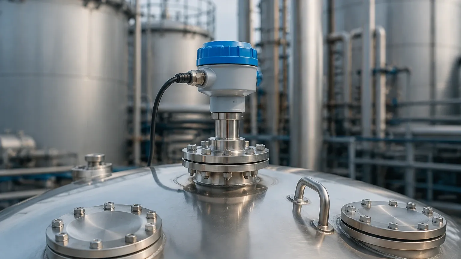
In the evolving landscape of industrial automation, the demand for high-precision instrumentation with a reduced physical footprint has led to the rise of the compact radar level transmitter. Traditionally, radar-based level measurement required bulky housings and large horn antennas to achieve the necessary signal focus and accuracy. However, advancements in high-frequency semiconductor technology—specifically the shift toward 80 GHz Frequency Modulated Continuous Wave (FMCW) radar—have enabled manufacturers like Welk to produce high-performance Radar Level Meters that fit into the palm of a hand.
This guide provides a technical overview of compact radar technology, its operating principles, selection criteria, and the practical constraints engineers must consider when integrating these sensors into industrial processes.
1. Measurement Principles of Compact Radar Transmitters
To understand why a compact radar level transmitter is effective, it is necessary to examine the underlying physics of radar measurement. Most modern compact units utilize FMCW technology rather than the older pulse-radar method.
FMCW (Frequency Modulated Continuous Wave)
In FMCW radar, the transmitter emits a continuous signal with a frequency that increases linearly over time (a frequency sweep or "chirp"). The signal travels to the product surface, reflects, and is received by the antenna. Because the transmitted frequency is constantly changing, there is a frequency difference between the signal currently being transmitted and the reflected signal received.
This frequency difference ($Δf$) is directly proportional to the time of flight and, consequently, the distance to the material surface. The relationship is expressed as:
$$d = \frac{c \cdot T \cdot \Delta f}{2 \cdot B}$$
Where:
* d is the distance.
* c is the speed of light.
* T is the sweep duration.
* B is the sweep bandwidth.
The Role of 80 GHz Technology
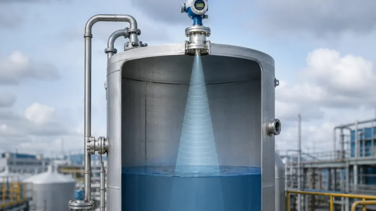
The move to the 80 GHz frequency band is the primary driver behind miniaturization. A higher frequency results in a shorter wavelength. In antenna theory, the beamwidth is inversely proportional to the antenna diameter and the frequency. By increasing the frequency to 80 GHz, a very narrow beam angle (often as low as 3° to 4°) can be achieved with a small antenna (e.g., 32 mm or 1.25 inches). This allows the compact radar level transmitter to be installed in small tanks or through narrow nozzles without interference from vessel walls or internal obstructions.
2. Technical Selection Criteria
When selecting a compact radar level transmitter, engineers must evaluate several technical parameters to ensure the device is compatible with the process environment.
Dielectric Constant (εr)
The dielectric constant of the medium is the most critical factor in signal reflection. Materials with high εr, such as water (εr ≈ 80), provide strong reflections. Low εr materials, such as hydrocarbons or plastic pellets (εr < 2), reflect less energy. Modern FMCW compact radars feature high sensitivity and dynamic range, allowing them to measure materials with εr as low as 1.4, provided the surface is relatively calm.
Measuring Range and Accuracy
Compact units are typically optimized for ranges between 10 meters (32.8 ft) and 30 meters (98.4 ft). While larger radar units can reach 100 meters (328 ft), the compact design focuses on accuracy in small-to-medium vessels, often achieving a precision of ±2 mm (0.078 in).
Process Conditions
* Temperature: Standard compact units typically handle process temperatures from -40°C to +80°C (-40°F to +176°F). For high-temperature applications, thermal decoupling or specialized housings are required.
* Pressure: Most compact plastic-housed units are rated for atmospheric pressure or low-pressure environments (up to 3 bar / 43.5 psi). Stainless steel versions can handle higher pressures.
Selection Table for Compact Radar Transmitters
| Feature | Entry-Level Compact | Industrial Compact | High-Precision Compact |
| :— | :— | :— | :— |
| Frequency | 26 GHz / 80 GHz | 80 GHz | 80 GHz |
| Max Range | 15 m (49.2 ft) | 30 m (98.4 ft) | 30 m (98.4 ft) |
| Accuracy | ±5 mm | ±2 mm | ±1 mm |
| Beam Angle | 8° – 10° | 4° – 6° | 3° |
| Housing Material | PVDF / Plastic | Stainless Steel / PBT | Stainless Steel |
| Output | 4-20mA / Modbus | 4-20mA / HART / Bluetooth | 4-20mA / HART / Profibus |
3. Installation Considerations and Constraints
Proper installation is vital to prevent "false echoes" and ensure reliable data. Even with the narrow beam of an 80 GHz compact radar level transmitter, certain geometric rules apply.
Mounting Position
* Distance from Wall: The sensor should not be mounted in the center of a tank (to avoid multiple reflections) nor too close to the wall (to avoid interference). A general rule is to mount the sensor at 1/4 to 1/3 of the tank diameter from the wall.
* Nozzle Height: The antenna should ideally extend slightly beyond the mounting nozzle. If the nozzle is long and narrow, the radar signal may reflect off the nozzle interior, creating a large "dead zone" at the top of the tank.
The Dead Zone (Blocking Distance)
The dead zone is the area immediately below the sensor where measurement is impossible. For a compact radar level transmitter, this is typically between 0.05 m and 0.1 m (2 to 4 inches). Engineers must ensure that the maximum expected liquid level does not enter this zone.
Obstructions
Internal structures like ladders, agitators, or heating coils can reflect the radar signal. While modern software allows for "False Signal Suppression" (where the transmitter learns to ignore static echoes), it is best practice to align the beam to avoid these objects entirely.
4. Application Environments and Limitations
Compact radar transmitters are versatile but not universal. Understanding their limitations prevents costly field failures.
Ideal Applications
1. Water and Wastewater: Monitoring levels in lift stations, flumes, and chemical dosing tanks. The non-contact nature prevents sensor fouling from grease or debris.
2. Chemical Storage: Small plastic or metal tanks containing acids or bases. Compact PVDF-encapsulated sensors offer excellent corrosion resistance.
3. Industrial Automation: Integration into skid-mounted systems where space is at a premium and Modbus or 4-20mA integration is required.
Limitations and Risks
* Heavy Foam: Dense, thick foam can absorb radar signals. If the foam is conductive and thick, the radar may measure the top of the foam or lose the signal entirely. In such cases, a guided wave radar or hydrostatic sensor may be more appropriate.
* Extreme Dust: While radar penetrates dust better than ultrasonic sensors, extremely high concentrations of metallic or conductive dust can attenuate the signal.
* Condensation: While 80 GHz radars handle condensation better than older models, heavy droplet formation on the antenna lens can cause signal deviation. Some compact units feature a convex lens design to encourage droplets to run off.
5. Information for International Procurement
When sourcing a compact radar level transmitter from an international manufacturer, buyers should confirm the following technical details to ensure compliance and compatibility:
1. Certifications: Does the device require ATEX/IECEx for hazardous areas? Is there a need for CE or RoHS compliance?
2. Communication Protocol: Ensure the output (e.g., 4-20mA, HART, RS485/Modbus) matches the existing PLC or SCADA system.
3. Process Connection: Confirm thread types (G, NPT) or flange standards (ANSI, DIN) to avoid installation delays.
4. Configuration Method: Many compact units are now configured via Bluetooth and a smartphone app. Confirm if this is permitted within the facility or if a physical programmer is required.
Frequently Asked Questions (FAQ)
Q: Can a compact radar level transmitter replace an ultrasonic sensor?
A: In most cases, yes. Radar is unaffected by air temperature, vacuum, pressure, or vapor layers, which often cause ultrasonic sensors to fail. The price gap between the two technologies has narrowed significantly, making radar a more robust choice for many applications.
Q: Does the color of the liquid affect the measurement?
A: No. Radar is an electromagnetic wave and is unaffected by the optical properties (color, transparency, or light levels) of the medium.
Q: How do I handle a tank with a spherical bottom?
A: For tanks with non-flat bottoms, the radar may lose the signal when the tank is nearly empty because the signal reflects away from the antenna. In these instances, the software can be configured to hold the last known value or report "empty" based on a calculated threshold.
Conclusion
The compact radar level transmitter represents a significant leap in process instrumentation, offering the precision of high-frequency FMCW radar in a form factor suitable for diverse industrial applications. By understanding the dielectric properties of the medium and adhering to strict installation guidelines, engineers can implement a maintenance-free level measurement solution that improves process reliability. For those seeking specific configurations or OEM solutions, exploring the range of Radar Level Meters is the first step toward optimizing industrial level control.