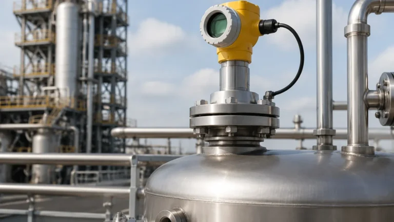
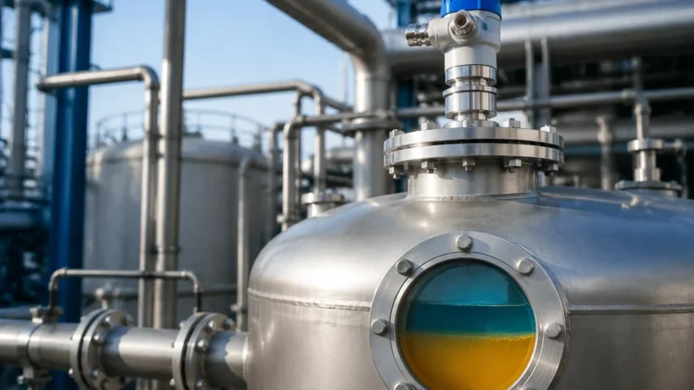
Coaxial Radar Level Transmitter
Coaxial Radar Level Transmitter: A Technical Guide to High-Precision Industrial Measurement
In the field of industrial process automation, the ability to accurately monitor liquid levels under challenging conditions is paramount for safety, efficiency, and inventory management. Among the various technologies available, Radar Level Meters have emerged as the gold standard for non-contact and contact-based measurement. Specifically, the coaxial radar level transmitter—a subset of Guided Wave Radar (GWR) technology—offers a unique set of advantages for measuring low-dielectric fluids, turbulent surfaces, and applications where internal tank obstructions would otherwise interfere with signal integrity.
This guide provides a comprehensive engineering overview of coaxial radar technology, its operating principles, selection criteria, and the practical considerations necessary for successful deployment in B2B industrial environments.
1. Measurement Principles: Understanding Guided Wave Radar (GWR)
To understand the coaxial radar level transmitter, one must first understand the fundamental principle of Guided Wave Radar. Unlike non-contact radar, which broadcasts electromagnetic pulses through the air, GWR utilizes a physical probe to guide the high-frequency microwave pulses from the sensor head to the process medium.
Time Domain Reflectometry (TDR)
At the core of this technology is Time Domain Reflectometry (TDR). The transmitter emits a low-energy pulse of microwaves that travels down the probe at the speed of light. When the pulse reaches the surface of the product being measured, the change in the dielectric constant ($ε_r$) causes a change in impedance, triggering a reflection.
The instrument measures the time-of-flight between the emission of the pulse and the reception of the echo. The distance ($D$) to the product surface is calculated using the formula:
$$D = \frac{c \times t}{2}$$
Where:
- $c$ is the speed of light (adjusted for the medium in the vapor space).
- $t$ is the measured transit time.
The Coaxial Advantage
In a coaxial configuration, the probe consists of an inner rod housed within an outer perforated tube or pipe. This design creates a "concentric" waveguide. The electromagnetic field is entirely contained within the space between the inner rod and the outer tube. This confinement prevents the signal from spreading into the tank, which eliminates interference from tank walls, internal ladders, agitators, or heating coils. Furthermore, because the energy is concentrated, the signal-to-noise ratio is significantly higher than that of single-rod or twin-rod probes.
2. Technical Comparison: Coaxial vs. Other Probe Types
Selecting the correct probe geometry is critical for the long-term reliability of Radar Level Meters. The following table outlines the performance characteristics of the coaxial radar level transmitter compared to other common GWR designs.
| Feature | Coaxial Probe | Single Rod Probe | Twin Rod Probe |
| :— | :— | :— | :— |
| Minimum Dielectric (ε_r) | ≥ 1.4 | ≥ 1.9 | ≥ 1.6 |
| Immunity to Obstructions | Excellent (Highest) | Poor | Moderate |
| Suitability for Foam | Moderate | Good | Fair |
| Viscous/Sticky Liquids | Not Recommended | Excellent | Poor |
| Interface Measurement | Best Performance | Good | Fair |
| Max Measurement Range | Typically up to 6m | Up to 30m+ | Up to 20m |
3. Key Advantages of Coaxial Radar Level Transmitters
High Sensitivity for Low-Dielectric Media
One of the most significant challenges in radar level measurement is detecting the surface of fluids with low dielectric constants, such as liquefied gases, solvents, and refined oils. In a standard rod probe, much of the signal energy is lost to the surrounding environment. The coaxial design ensures that the maximum amount of energy is reflected back to the sensor, allowing for the reliable measurement of fluids with dielectric constants as low as 1.4.
Immunity to Nozzle Interference
The geometry of the mounting nozzle can often create "ringing" or false echoes in non-contact radar and single-rod GWR systems. Because the coaxial probe acts as its own waveguide, the signal is shielded from the nozzle. This allows for installation in narrow nozzles or even nozzles with internal welds and imperfections.
Superior Interface Measurement
Coaxial probes are the preferred choice for liquid-liquid interface measurement (e.g., oil over water). The concentrated field allows the transmitter to clearly distinguish between the upper layer (low Dk) and the lower layer (high Dk), provided the upper layer is non-conductive and has a lower dielectric constant than the lower layer.
4. Selection Criteria for Industrial Applications
When specifying a coaxial radar level transmitter for a project, international buyers and engineers must evaluate several environmental and chemical factors.
Material Compatibility
The standard material for coaxial probes is usually 316L stainless steel. However, for corrosive applications involving acids or chlorides, specialized alloys like Hastelloy C-276 or PTFE-coated components may be required. Ensure that the O-ring seals (Viton, Kalrez, or EPDM) are compatible with the process vapors.
Pressure and Temperature Ratings
Industrial processes often operate at extremes. Coaxial transmitters can be engineered to handle temperatures from -200°C (cryogenic) to +450°C and pressures ranging from full vacuum to 400 bar (40 MPa). It is essential to confirm the flange rating (e.g., ASME B16.5 or EN 1092-1) matches the vessel requirements.
Process Medium Characteristics
While coaxial probes are technically superior in signal strength, they are physically restrictive. They should be avoided if the medium is:
- Highly Viscous: Fluids that do not flow easily may bridge the gap between the rod and the tube.
- Prone to Coating: If the medium leaves a thick, conductive film on the probe, it will cause measurement errors.
- Containing Large Solids: Particulates can become trapped inside the tube, leading to false high-level readings.

5. Installation Considerations and Best Practices
To ensure the accuracy of a coaxial radar level transmitter, follow these engineering guidelines during the installation phase:
1. Vertical Alignment: The probe must be installed vertically. Any significant tilt can cause the inner rod to touch the outer tube, creating a short circuit in the electromagnetic pulse and resulting in a "loss of echo" error.
2. Venting and Drainage: Ensure the coaxial tube has vent holes at the top (to allow air/vapor to escape as the level rises) and drainage holes at the bottom. If these are blocked, the level inside the tube will not match the level in the tank.
3. Nozzle Clearance: While coaxial probes are immune to nozzle interference, the flange connection must be secure. Ensure the nozzle diameter is large enough to accommodate the outer diameter of the coaxial tube (typically 22mm to 42mm depending on the model).
4. Bypass Chambers: Coaxial probes are frequently installed in external bypass chambers (bridles). This is an excellent way to isolate the instrument for maintenance without depressurizing the main vessel.
6. Limitations and Application Risks
Engineers must be aware of the "Dead Zones" or "Blocking Distances" associated with GWR technology.
- Upper Dead Zone: The area near the flange where measurement is not possible (typically 100mm to 300mm).
- Lower Dead Zone: The area at the very tip of the probe where the signal reflection becomes non-linear (typically 50mm to 100mm).
If the liquid level enters these zones, the transmitter may output an error signal or hold the last valid value. Always size the probe length so that the operating range of the tank falls within the active measurement zone of the transmitter.
7. Frequently Asked Questions (FAQ)
Q: Can a coaxial radar level transmitter measure solids or powders?
A: Generally, no. Solids can bridge the gap between the inner and outer conductors, causing immediate failure. Single-rod GWR or non-contact radar is preferred for bulk solids.
Q: How does steam affect the measurement?
A: High-pressure steam can change the dielectric constant of the vapor space, which slows down the radar pulse and causes a "distance error" (the level appears lower than it is). High-end coaxial transmitters often include "End of Probe" (EOP) shift compensation or a reference reflection to automatically correct for steam-induced errors.
Q: Is maintenance required for the coaxial tube?
A: In clean liquid applications, maintenance is minimal. However, if the process involves fluids that may crystallize or precipitate over time, periodic inspection and cleaning of the internal rod and tube are necessary to prevent buildup.
Q: What is the maximum length for a coaxial probe?
A: Due to the weight and the risk of the inner rod bending, rigid coaxial probes are usually limited to 6 meters. For longer distances, flexible cable-style GWR probes are used, though these lose the specific "coaxial" waveguide benefits unless installed in a dedicated bypass pipe.
Conclusion
The coaxial radar level transmitter represents a highly specialized solution within the broader category of Radar Level Meters. By confining the electromagnetic signal within a dedicated waveguide, it provides unparalleled accuracy for low-dielectric liquids and complex tank geometries. For B2B buyers and plant engineers, selecting this technology requires a careful balance between the need for signal precision and the physical characteristics of the process medium. When applied correctly, it offers a robust, maintenance-free solution for the most demanding level measurement tasks in the chemical, oil and gas, and power industries.