Radiation Tracker
Radiation Tracker
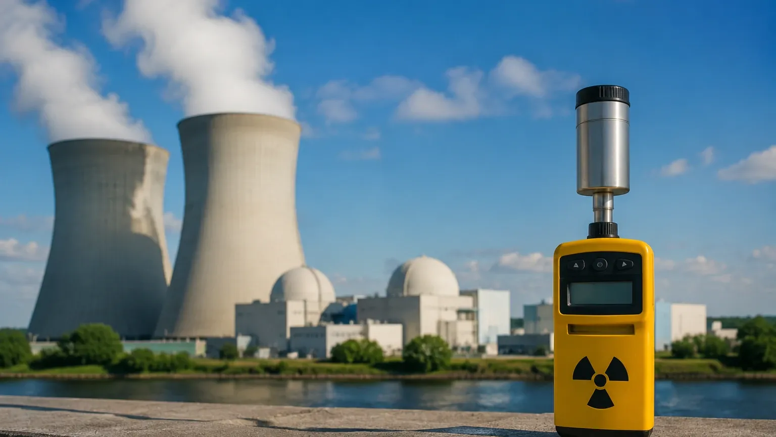
In the landscape of industrial process control, certain environments present challenges that render traditional contact-based or even standard non-contact sensors ineffective. High-pressure reactors, vessels containing highly corrosive acids, and molten metal furnaces require a level measurement solution that operates entirely outside the process container. This is where the radiation tracker, the core component of a radiometric level measurement system, becomes essential. By utilizing the principle of gamma radiation attenuation, these systems provide highly accurate, continuous, or point-level data without ever touching the medium being measured.
Fundamental Principles of Radiometric Level Measurement
To understand the function of a radiation tracker, one must first understand the physics of gamma radiation attenuation. Radiometric measurement is based on the Beer-Lambert Law, which describes how the intensity of radiation decreases as it passes through matter.
When a radioactive source—typically Cesium-137 (Cs-137) or Cobalt-60 (Co-60)—emits gamma rays, those rays travel through the vessel walls and the internal medium. As the rays encounter atoms in the medium, they are absorbed or scattered. The amount of radiation that reaches the detector (the radiation tracker) on the opposite side of the vessel is inversely proportional to the mass of the material in the path of the beam.
In a level measurement application, the source and the tracker are mounted on opposite sides of the tank. If the tank is empty, the tracker receives a high level of radiation. As the liquid or solid level rises and enters the path between the source and the tracker, it absorbs a portion of the gamma rays. The tracker measures this reduction in intensity and converts it into a standardized electronic signal, such as a 4-20 mA output, representing the level of the material.
Components of a Radiation Tracker System
A complete radiometric measurement loop consists of several critical components, each designed to ensure both measurement accuracy and operational safety:
1. Radioactive Source: Usually a small ceramic pellet containing the isotope, double-encapsulated in stainless steel to prevent leakage.
2. Source Holder (Collimator): A heavy, lead-lined or tungsten container that houses the source. It features a narrow slit or "shutter" that allows radiation to exit only in the direction of the vessel and the tracker, shielding all other directions.
3. The Radiation Tracker (Detector): This is the sensing element. Modern trackers typically use a scintillation crystal (such as Sodium Iodide) or a specialized polymer. When gamma photons hit the scintillator, they produce flashes of light, which are converted into electrical pulses by a photomultiplier tube or a high-sensitivity photodiode.
4. Electronic Transmitter: Integrated into the tracker, this component processes the pulse frequency, compensates for the natural decay of the radioactive source, and filters out background cosmic radiation to provide a clean level signal.
Key Applications in Process Industries
The radiation tracker is rarely the first choice for simple water tank applications due to regulatory requirements, but it is the definitive solution for "impossible" measurements. Key sectors include:
* Chemical and Petrochemical: Monitoring levels in high-pressure polymerization reactors where the internal environment is too volatile or viscous for radar or ultrasonic sensors.
* Mining and Minerals: Measuring the level of abrasive slurries or the density of material in a cyclone separator. Since the tracker is external, it is not subject to the wear and tear of the abrasive media.
* Steel and Metal Production: Continuous casting processes use radiation trackers to monitor the level of molten steel in a mold. The extreme heat (exceeding 1,500°C) makes any internal sensor impossible.
* Oil and Gas: Separator vessels where foam, emulsion layers, and high pressure make interface measurement difficult for standard technologies.
For engineers evaluating these specialized tools alongside more common instruments like radar or ultrasonic sensors, the Main Page of technical catalogs provides a starting point for comparing performance specifications across different measurement categories.
Selection Criteria for Radiation-Based Instrumentation
Choosing the right radiation tracker system requires a detailed analysis of the vessel geometry and the material properties. The following table outlines the primary considerations for selection:
| Selection Factor | Consideration | Impact on Tracker Choice |
| :— | :— | :— |
| Vessel Diameter | Distances over 2 meters | May require a higher activity source or a more sensitive scintillation tracker. |
| Wall Thickness | Steel walls > 50 mm | Significant baseline attenuation; requires high-energy isotopes like Co-60. |
| Measurement Range | Continuous vs. Point | Point level requires a small detector; continuous level requires a long "rod" detector or a detector array. |
| Material Density | Low-density gases vs. high-density solids | Lower density materials require more sensitive trackers to detect subtle changes in attenuation. |
| Ambient Temperature | High heat near the vessel | Trackers may require water-cooling jackets to protect the internal electronics. |
| Safety Regulations | Local nuclear regulatory laws | Determines the maximum allowable source activity and required shielding thickness. |
Installation and Safety Guidelines
Installation of a radiation tracker is a specialized task that must comply with both engineering best practices and strict legal frameworks.
Mounting Configurations
There are two primary ways to mount a radiation tracker for continuous level measurement:
1. Point Source and Rod Detector: A single source is mounted at the top of the measurement range, and a long, vertical tracker is mounted on the opposite side. This is common for ranges up to 3 meters.
2. Rod Source and Point Detector: A long, strip-like source is used with a small point detector. This is often used when space on the detector side is limited.
Shielding and Collimation
The source holder must be selected to ensure that the radiation dose rate at the surface of the container is within safe limits (usually < 5 µSv/h at 1 meter). The "beam angle" must be precisely aligned with the tracker to prevent "stray" radiation from increasing the background noise or posing a risk to personnel.
Calibration
Calibration involves two steps: the "Empty Calibration" (measuring the radiation intensity when the vessel is empty) and the "Full Calibration" (measuring intensity at a known high level). Because radioactive isotopes decay over time (Cs-137 has a half-life of approximately 30 years), the tracker's software must include a decay compensation algorithm to maintain accuracy over the decades of the instrument's lifespan.
Comparison with Alternative Level Measurement Technologies
While the radiation tracker is highly effective, it is often compared with other non-contact methods. The following table highlights the differences:
| Feature | Radiation Tracker | Non-Contact Radar | Ultrasonic Sensor |
| :— | :— | :— | :— |
| Contact with Media | None (External) | None (Internal/Top) | None (Internal/Top) |
| Pressure Limits | Unlimited (Vessel dependent) | Up to 160 bar (typical) | Usually < 3 bar |
| Temperature Limits | Unlimited (Vessel dependent) | Up to 450°C | Up to 150°C |
| Installation Complexity | High (Regulatory/Shielding) | Moderate | Low |
| Maintenance | Low (No moving parts) | Low | Low |
| Cost | High | Moderate | Low |
Limitations and Practical Considerations
Despite its versatility, the radiation tracker has specific limitations that engineers must account for:
* Regulatory Burden: The use of radioactive sources requires licensing, specialized training for Radiation Safety Officers (RSOs), and periodic leak testing (wipe tests).
* Build-up on Walls: If the process material tends to stick to the vessel walls, the tracker will interpret this build-up as a constant level, leading to measurement errors. This is known as the "scaling effect."
* Gas Density Changes: In very high-pressure applications, changes in the density of the gas phase (the space above the liquid) can attenuate the radiation, causing a false high-level reading. Modern trackers can use a second "reference" detector to compensate for gas density shifts.
* Source Decay: Although predictable, the weakening of the source over time reduces the signal-to-noise ratio, eventually requiring source replacement after 15 to 30 years.
Frequently Asked Questions (FAQs)
Q: Is the material being measured made radioactive by the tracker?
No. Gamma radiation at the energy levels used in industrial measurement (Cs-137 or Co-60) does not have enough energy to induce radioactivity in the process material. The material is only exposed to the beam, not contaminated by it.
Q: What happens if the power fails?
The source holder is equipped with a mechanical shutter. In the event of a power failure or fire, the shutter can be closed (often automatically via a spring-return pneumatic actuator) to completely block the radiation beam.
Q: How accurate is a radiation tracker?
Under stable conditions, a radiation tracker can achieve an accuracy of ±1% of the measurement range. However, accuracy is highly dependent on the stability of the material's bulk density.
Q: Can a radiation tracker measure interface levels?
Yes. If two liquids have significantly different densities (e.g., oil and water), the tracker can detect the change in attenuation at the interface layer, provided the density difference is at least 0.1 g/cm³.
For professionals seeking to integrate these systems into a broader automation strategy, reviewing the technical documentation and product options on the Main Page is recommended to ensure the selected technology aligns with specific industrial safety and performance standards.