Tsunami Detection System
Tsunami Detection System
A tsunami detection system is a sophisticated network of sensors and communication technologies designed to identify, verify, and report the generation of tsunamis in real-time. For engineers and municipal planners, these systems represent the critical bridge between seismic activity and public safety. While the primary trigger for a tsunami is often an undersea earthquake, the detection system itself relies heavily on advanced level measurement technologies to distinguish between normal tidal variations and the lethal energy of a tsunami wave.
In the context of industrial and environmental monitoring, the principles used in a tsunami detection system mirror those found in high-precision level measurement for large-scale water treatment and coastal management. Understanding the sensors, data transmission protocols, and installation requirements is essential for developing a reliable early warning infrastructure.
Measurement Principles in Tsunami Detection
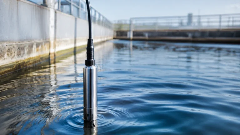
Effective detection requires measuring changes in sea level with millimeter precision across vast oceanic distances. Two primary measurement principles dominate the field: hydrostatic pressure sensing and non-contact radar level measurement.
Hydrostatic Pressure Sensing
Hydrostatic sensors are typically deployed on the seafloor. The principle is based on the relationship between the height of the water column and the pressure exerted at the base. The formula $P = \rho gh$ (where $P$ is pressure, $
ho$ is water density, $g$ is gravity, and $h$ is the height of the water) allows the system to calculate the exact depth of the ocean above the sensor.
When a tsunami passes over a deep-ocean sensor, the increased volume of water causes a momentary spike in hydrostatic pressure. These sensors must be sensitive enough to detect a change of less than 1 cm in water depths exceeding 5,000 meters. To achieve this, high-resolution quartz pressure transducers are often employed due to their stability and low drift over time.
Radar Level Measurement (Non-Contact)
Coastal monitoring stations frequently utilize radar level meters. Unlike hydrostatic sensors that sit on the seabed, radar units are mounted on piers, bridges, or specialized platforms above the water surface. They emit high-frequency microwave pulses (typically in the 26 GHz or 80 GHz range) that reflect off the water's surface.
By measuring the Time-of-Flight (ToF) of the pulse, the system calculates the distance to the water surface. Radar is preferred for coastal applications because it is non-contact, meaning the sensor is not subject to corrosion, biofouling, or damage from floating debris. This technology provides a continuous stream of sea-level data that can be compared against predicted tide tables to identify anomalies.
Key Components of a Tsunami Detection System
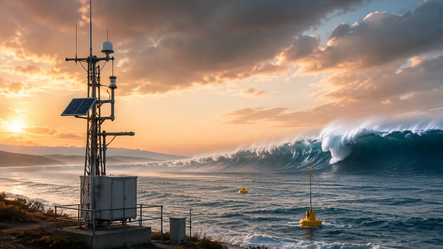
A functional system is composed of three main segments: the sensing unit, the surface buoy (for deep-sea systems), and the satellite/ground processing center.
1. Bottom Pressure Recorder (BPR): This is the "ear" of the system. It sits on the ocean floor and monitors pressure 24/7. It includes internal processing to filter out high-frequency noise from surface waves, focusing only on the long-period waves characteristic of a tsunami.
2. Acoustic Modem: Because radio waves do not travel well through water, the BPR uses acoustic pulses to transmit data to a buoy floating on the surface.
3. Surface Buoy: The buoy acts as a relay station. It receives acoustic data from the seafloor, processes it, and transmits it via satellite (such as Iridium) to monitoring centers. It also contains GPS for positioning and solar panels for power.
4. Coastal Tide Gauges: These are the secondary line of defense, often utilizing radar or ultrasonic sensors to confirm the arrival of a wave at the shoreline and provide data on wave height and inundation levels.
Technical Selection Criteria
Selecting the right instrumentation for a tsunami detection system or related coastal monitoring project requires evaluating several technical parameters. The following table compares the primary technologies used in these environments:
| Feature | Hydrostatic (Deep Sea) | Radar (Coastal) | Ultrasonic (Inland/Harbor) |
| :— | :— | :— | :— |
| Measurement Range | Up to 7,000 m | Up to 70 m | Up to 15 m |
| Accuracy | ±0.01% of Full Scale | ±2 mm | ±0.25% of Range |
| Installation | Seafloor deployment | Above-water mounting | Above-water mounting |
| Maintenance | High (requires vessels) | Low (accessible) | Moderate (cleaning sensor face) |
| Environmental Resistance | High Pressure, Salinity | Wind, Fog, Temperature | Affected by wind/temp gradients |
| Power Consumption | Very Low (Battery) | Moderate (Solar/Mains) | Moderate |
For professionals seeking to implement robust level monitoring in industrial or environmental sectors, reviewing a wide range of Main Page options is recommended to ensure the technology matches the specific environmental constraints of the site.
Installation and Engineering Considerations
Deploying a tsunami detection system involves significant engineering challenges, particularly regarding the longevity of the equipment in harsh marine environments.
Material Selection
Corrosion is the primary enemy of marine instrumentation. Sensors and housing units must be constructed from high-grade materials such as Titanium, 316L Stainless Steel, or specialized plastics like PTFE. For hydrostatic sensors, the diaphragm is the most sensitive component and often requires specialized coatings to prevent biofouling—the accumulation of microorganisms, algae, or barnacles—which can distort pressure readings.
Data Sampling and Filtering
One of the most complex aspects of a tsunami detection system is data filtering. The ocean surface is never still; it is influenced by wind waves, swells, and tides. A detection system must use sophisticated algorithms to "smooth" the data. In deep-sea sensors, this is often done by averaging pressure readings over a period (e.g., 15 seconds to 1 minute) to eliminate the noise of surface gravity waves while retaining the signal of the long-wavelength tsunami.
Redundancy and Power
Remote systems must be self-sufficient. This typically involves dual-redundant sensors and high-capacity battery banks supplemented by solar power. In industrial level measurement, redundancy ensures that a single sensor failure does not lead to a system-wide shutdown. In tsunami detection, redundancy is a matter of life safety.
Limitations and Challenges
While modern tsunami detection systems are highly advanced, they are not without limitations. Understanding these risks is vital for any engineering project involving environmental monitoring.
* False Alarms: Underwater landslides or large seismic events that do not displace enough water to cause a tsunami can still trigger sensors. Advanced systems use "Tsunami Detection Algorithms" to compare the rate of change in water level against known tsunami profiles to reduce false positives.
* The "Blind Zone": Sensors placed too close to the earthquake epicenter may not provide enough lead time for a warning. Conversely, sensors placed too far away may delay the warning for local populations. Strategic placement is a balance of geography and bathymetry.
* Telemetry Latency: Relying on satellite communication introduces a small but critical delay. In a B2B or industrial context, this is comparable to the latency in SCADA systems, where real-time data is required for automated safety shut-offs.
* Maintenance Logistics: Servicing a deep-ocean BPR requires specialized ships and ROVs (Remotely Operated Vehicles), making the operational cost of these systems significantly higher than land-based level measurement stations.
Frequently Asked Questions (FAQ)
Q: How does a tsunami detection system differ from a standard tide gauge?
A: While both measure sea level, a tsunami detection system operates at a much higher sampling frequency and is equipped with specific algorithms to detect rapid, non-tidal changes in water height. Standard tide gauges may only report data every 6 to 15 minutes, which is too slow for tsunami early warning.
Q: Can radar level meters work during heavy storms or rain?
A: Yes, high-frequency radar (especially 80 GHz) is designed to penetrate fog, rain, and steam. However, extreme surface turbulence caused by storm surges can scatter the radar signal. In these cases, a stilling well is often used to provide a calm surface for the radar to measure.
Q: Why is hydrostatic pressure used in the deep ocean instead of ultrasonic sensors?
A: Ultrasonic sensors rely on sound waves traveling through air. In the deep ocean, there is no air-water interface to measure from the bottom up using ultrasound. Furthermore, the power required to send an ultrasonic pulse through 5,000 meters of water and receive a return signal is prohibitively high compared to the passive measurement of hydrostatic pressure.
Q: What is the lifespan of these sensors?
A: In a typical industrial environment, high-quality level sensors can last 10-15 years. In a marine tsunami detection system, the sensors themselves are durable, but the batteries and acoustic modems usually require servicing or replacement every 2 to 4 years.
Conclusion and Project Confirmation
Implementing a tsunami detection system requires a deep understanding of fluid dynamics, electronic instrumentation, and marine engineering. For project managers and engineers, the first step is to confirm the specific environmental conditions of the deployment site, including maximum expected wave heights, water depth, and the availability of communication infrastructure.
Whether you are designing a coastal defense network or an industrial water management system, the choice of level measurement technology is the foundation of reliability. For those in the planning stages of a monitoring project, it is essential to consult with instrumentation experts who can provide tailored advice on sensor selection and system integration. You can explore a variety of professional-grade measurement tools and technical support by visiting the Main Page for comprehensive product specifications and application guides.