Vega Corp
Vega Corp
In the landscape of industrial automation and process control, Vega Corp (VEGA Grieshaber KG) stands as a primary benchmark for level and pressure measurement instrumentation. For engineers and procurement specialists, understanding the technological foundations laid by industry leaders is essential when evaluating high-precision sensors for complex environments. This guide explores the core measurement principles, selection criteria, and practical installation considerations that define modern level measurement, providing a framework for comparing market-leading solutions with specialized alternatives available on our Main Page.
1. Core Principles of Level Measurement
Before selecting a specific instrument, it is vital to understand the physics governing the measurement. Industrial level sensors generally fall into two categories: non-contact and contact-based measurement.
Radar Level Measurement (ToF)
Radar technology, pioneered in the industrial sector by companies like Vega Corp, operates on the Time-of-Flight (ToF) principle. The sensor emits a high-frequency microwave signal (typically in the 6 GHz, 26 GHz, or 80 GHz range) toward the medium. The signal reflects off the surface and returns to the sensor. The distance is calculated using the formula:
$$D = \frac{c \times t}{2}$$
Where:
* D is the distance to the medium.
* c is the speed of light.
* t is the measured transit time.
Modern 80 GHz radar sensors offer a narrow beam angle, which minimizes interference from tank internals such as agitators or heating coils. This technology is highly valued for its immunity to temperature fluctuations, vacuum conditions, and high pressure.
Ultrasonic Level Measurement
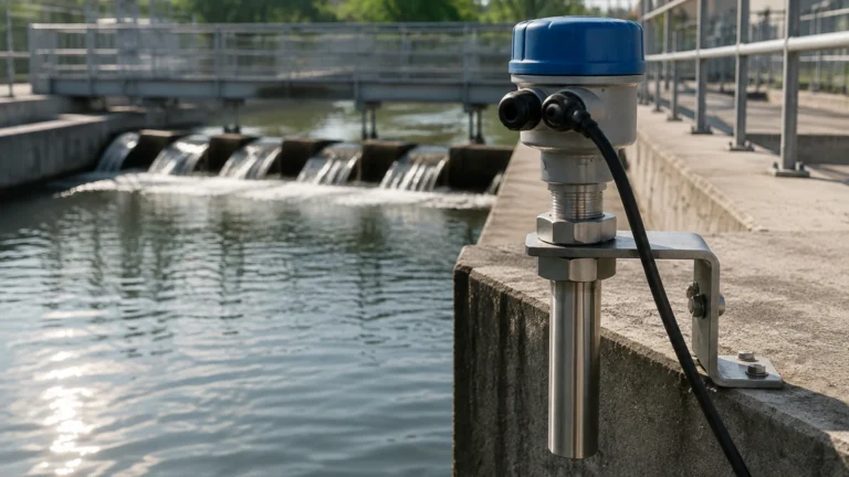
Ultrasonic sensors utilize sound waves rather than electromagnetic waves. A transducer emits mechanical pulses that bounce off the liquid or solid surface. While cost-effective, ultrasonic measurement is influenced by the medium's air temperature, as the speed of sound varies with air density. These are ideal for open-channel flow and atmospheric water tanks but are limited in vacuum or high-dust environments.
Hydrostatic Pressure Measurement
Hydrostatic transmitters measure the pressure exerted by a liquid column. The principle is based on the relationship between pressure, density, and height:
$$P = \rho \times g \times h$$
Where:
* P is the hydrostatic pressure.
* ρ (rho) is the density of the liquid.
* g is the gravitational constant.
* h is the height of the liquid.
This method is highly reliable for vented tanks where the liquid density remains constant. It is a staple in water treatment and chemical storage.
2. Comparative Technology Table
When evaluating instruments from Vega Corp or other professional manufacturers like Welk, the following table serves as a quick reference for technology selection:
| Technology | Typical Accuracy | Max Range | Key Advantages | Major Limitations |
| :— | :— | :— | :— | :— |
| 80 GHz Radar | ±1 mm | Up to 120 m | Non-contact, ignores foam/steam | High initial cost |
| Guided Wave Radar | ±2 mm | Up to 75 m | Works in low dielectric media | Contact-based (probe fouling) |
| Ultrasonic | ±0.2% of range | Up to 30 m | Cost-effective, simple setup | Sensitive to wind/vapor |
| Hydrostatic | ±0.1% to 0.5% | Dependent on SG | Easy to install, very stable | Requires constant density |
| Magnetic Gauge | Visual + Switch | Up to 6 m | No power needed for visual | Mechanical moving parts |
3. Evaluation Criteria for Industrial Applications
Selecting a level meter involves more than just matching a brand name. Engineers must confirm several technical variables to ensure long-term reliability and accuracy.
Dielectric Constant (εr)
For radar measurement, the reflectivity of the medium is determined by its dielectric constant. Materials with a low εr (such as oils or liquefied gases) reflect less energy than water-based liquids. If the εr is below 1.4, Guided Wave Radar (GWR) or high-sensitivity 80 GHz non-contact radar is usually required.
Process Conditions
* Temperature: Standard sensors typically handle up to 80°C. High-temperature versions with cooling fins or specialized ceramic seals can extend this to 450°C.
* Pressure: While ultrasonic sensors are limited to near-atmospheric pressures, radar and hydrostatic sensors can operate in environments exceeding 160 bar (16 MPa).
* Chemical Compatibility: The wetted parts (the parts of the sensor in contact with the media) must be resistant to corrosion. Common materials include 316L Stainless Steel, PTFE, PVDF, and Hastelloy.
Accuracy vs. Repeatability
In B2B process control, repeatability is often more critical than absolute accuracy. If a sensor consistently reports the same level under the same conditions, the control loop can be tuned effectively. High-end sensors from Vega Corp and Welk prioritize both, ensuring that batching processes remain consistent over thousands of cycles.
4. Installation Considerations and Best Practices
Proper installation is the most significant factor in preventing "false echoes" or signal loss. Regardless of whether you are installing a radar unit or an ultrasonic sensor, follow these engineering guidelines:
1. Avoid the Dead Zone: Every sensor has a "blocking distance" or dead zone near the antenna where measurement is impossible. Ensure the sensor is mounted high enough that the maximum liquid level never enters this zone.
2. Nozzle Geometry: For radar, the antenna should ideally extend slightly past the mounting nozzle to prevent signal ringing within the pipe. If the nozzle is long and narrow, an 80 GHz sensor is preferred due to its focused beam.
3. Positioning: Do not mount the sensor in the center of a domed tank, as this can concentrate parasitic reflections. Similarly, avoid mounting directly over the filling inlet, as the turbulence and falling product will interfere with the signal.
4. Obstacle Mapping: Modern instruments allow for "False Signal Suppression." During commissioning, the sensor can be programmed to ignore static reflections from ladders, pipes, or agitator blades.

5. Common Risks and Limitations
Even with advanced technology from Vega Corp, certain environmental factors can pose risks to measurement integrity:
* Build-up and Fouling: In wastewater or cement silos, material can accumulate on the sensor face. While radar can often "see through" thin layers of build-up, heavy coating will eventually attenuate the signal.
* Heavy Foam: Thick, dense foam can absorb radar signals entirely. In these cases, a displacement-type transmitter or a specialized low-frequency radar may be necessary.
* Vapor and Condensation: While radar is largely unaffected by vapor, ultrasonic waves are significantly slowed by heavy gas layers, leading to measurement errors. Condensation on an ultrasonic transducer can also cause the sensor to "lock" on a high-level reading.
6. Maintenance and Lifecycle Management
Industrial level meters are designed for longevity, but a routine maintenance schedule is recommended for mission-critical applications.
* Annual Calibration: Verify the sensor output against a manual tape measure or a secondary reference point.
* Seal Inspection: In pressurized vessels, check the integrity of process seals and cable glands to prevent moisture ingress into the electronics housing.
* Firmware Updates: Manufacturers frequently release updates to improve signal processing algorithms. Ensure your technical team has the tools to interface with the sensors via HART, Profibus, or Bluetooth protocols.
For those seeking reliable, cost-effective alternatives to the high-premium models often associated with Vega Corp, our engineering team provides a range of industrial-grade solutions. You can Review product options and application support to find the specific instrument that matches your process requirements.
7. Frequently Asked Questions (FAQ)
Q: Can radar level meters measure solids?
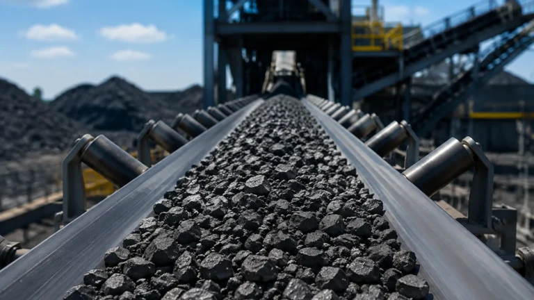
A: Yes. However, solids measurement requires sensors with higher sensitivity and specialized signal processing to account for the uneven surface (angle of repose) and dust generated during filling.
Q: What is the difference between 26 GHz and 80 GHz radar?
A: The 80 GHz radar has a much shorter wavelength, allowing for a smaller antenna and a much tighter beam angle (often as narrow as 3°). This makes it superior for small tanks or tanks with many internal obstructions.
Q: Is Guided Wave Radar (GWR) better than non-contact radar?
A: Not necessarily. GWR is superior for low-dielectric liquids and applications with heavy foam, but it is a contact technology, meaning the probe is subject to corrosion and mechanical stress. Non-contact radar is preferred for corrosive or abrasive media where minimal maintenance is desired.
Q: How do I handle measurement in a vacuum?
A: Radar is the preferred technology for vacuum applications because electromagnetic waves do not require a medium (like air) to travel. Ultrasonic sensors will not work in a vacuum.
By following these technical guidelines and understanding the fundamental principles used by leaders like Vega Corp, process engineers can make informed decisions that balance performance, reliability, and budget. For further technical specifications and customized OEM/ODM services, visit our Main Page.