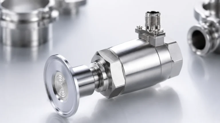
Radiation Gauge
Radiation Gauge
In the landscape of industrial process control, the radiation gauge—often referred to as a nucleonic gauge or gamma gauge—represents the ultimate solution for level and density measurement in extreme environments. Unlike contact-based sensors or even standard non-contact technologies like radar and ultrasonic, a radiation gauge operates entirely outside the process vessel. This non-intrusive nature makes it indispensable for applications involving high pressures, extreme temperatures, toxic media, or highly abrasive materials where other instruments would fail or require frequent, costly maintenance.
As industrial processes become more complex, understanding the technical nuances of radiation-based measurement is critical for plant engineers and instrumentation specialists. This guide provides a comprehensive technical overview of how these systems function, their primary components, selection criteria, and the safety protocols required for their implementation.
Understanding the Measurement Principle of Radiation Gauges
The operation of a radiation gauge is based on the principle of photon attenuation. When gamma radiation passes through matter, its intensity decreases according to the density and thickness of the material it encounters. This relationship is mathematically described by the Beer-Lambert Law:
**I = I₀ * e^(-μρd)**
Where:
* I is the intensity of radiation reaching the detector.
* I₀ is the initial intensity of the radiation source.
* μ is the mass attenuation coefficient of the material.
* ρ (rho) is the density of the material.
* d is the path length (the distance the radiation travels through the material).
In a level measurement application, the radiation gauge is mounted on the outside of a vessel. A radioactive source is housed in a shielded container on one side, and a sensitive detector is mounted on the opposite side. If the vessel is empty, the detector receives a high level of radiation. As the material level rises and enters the path between the source and the detector, it absorbs or scatters a portion of the gamma rays, causing the radiation intensity at the detector to drop. The electronics then convert this change in intensity into a proportional level or density signal.
Key Components of a Nucleonic Measurement System
A complete radiation gauge system consists of three primary elements: the radioactive source, the source holder (shielding), and the detector.
1. The Radioactive Source
Most industrial radiation gauges utilize either Cesium-137 (Cs-137) or Cobalt-60 (Co-60).
* Cesium-137: The most common choice due to its long half-life of approximately 30.17 years, which ensures long-term stability and reduces the frequency of source replacement.
* Cobalt-60: Used primarily for very thick-walled vessels or high-density materials because it emits higher-energy gamma rays. However, it has a shorter half-life of about 5.27 years, requiring more frequent recalibration and eventual replacement.
2. The Source Holder (Shielding)
Safety is paramount when using a radiation gauge. The source is encapsulated in a double-walled stainless steel capsule, which is then placed inside a source holder. This holder is typically constructed of lead or tungsten encased in a steel shell. It features a "shutter" mechanism that can be closed to block the radiation beam during maintenance or transport, ensuring that radiation levels outside the holder remain within regulatory limits.
3. The Detector
Modern detectors are highly sensitive and designed to operate with the lowest possible source activity. There are two main types:
* Scintillation Detectors: These use a crystal (often Sodium Iodide) or a plastic scintillator that produces flashes of light when struck by gamma rays. A photomultiplier tube or photodiode converts these light flashes into electrical pulses.
* Ionization Chambers: These consist of a gas-filled cylinder. Radiation ionizes the gas, creating a measurable electrical current. While robust, they are generally less sensitive than scintillation detectors.
Application Scenarios for Radiation Gauges
Radiation gauges are rarely the first choice for simple water tank level measurement due to the regulatory requirements associated with radioactive materials. However, they are the preferred technology in the following scenarios:
* High-Pressure Reactors: In chemical processing, reactors may operate at pressures exceeding 200 bar. A radiation gauge requires no vessel penetrations, eliminating potential leak paths.
* Extreme Temperatures: For molten metals or glass, where temperatures exceed 1,000°C (1,832°F), external mounting ensures the sensor is protected from the heat.
* Abrasive Slurries: In mining and mineral processing, slurries can quickly erode internal probes. Radiation gauges measure through the pipe or vessel wall, unaffected by the internal medium.
* Corrosive Acids: Measuring levels of hydrofluoric acid or other highly reactive chemicals is simplified when the instrument never touches the liquid.
* Coking and Fouling: In oil refineries, heavy crude can coat internal sensors. Because gamma rays pass through the buildup (provided it is accounted for during calibration), the gauge remains accurate.
For engineers evaluating these systems for specific industrial automation projects, it is helpful to Review product options and application support on the Welk Main Page to ensure the selected technology aligns with the specific process constraints.
Selection Criteria and Technical Specifications
Choosing the right radiation gauge requires a detailed analysis of the vessel and the process material. The following table outlines the key parameters that must be confirmed before procurement:
| Parameter | Consideration | Impact on Selection |
| :— | :— | :— |
| Vessel Diameter | Distance between source and detector. | Determines required source activity (mCi/GBq). |
| Wall Thickness | Material and thickness of vessel walls/insulation. | Affects radiation attenuation; may require Co-60 for heavy walls. |
| Material Density | Specific gravity of the process medium. | Higher density requires stronger sources or more sensitive detectors. |
| Measurement Range | Vertical height to be measured. | Determines if a point source or a strip source/detector array is needed. |
| Ambient Temperature | Temperature at the detector mounting location. | Detectors may require water-cooling jackets if exceeding 50°C to 60°C. |
| Accuracy Required | Typically ±1% to ±5% of span. | Influences the choice of detector type and integration time. |
Installation and Commissioning Best Practices
Proper installation is critical for both measurement accuracy and safety. Unlike ultrasonic or radar sensors, a radiation gauge must be perfectly aligned to ensure the radiation beam strikes the active area of the detector.
1. Alignment: The source holder and detector must be mounted precisely opposite each other. On large vessels, laser alignment tools are often used during the bracket installation phase.
2. Mounting Brackets: Because these instruments are heavy (especially the lead-shielded source holders), mounting brackets must be vibration-resistant and capable of supporting the weight over the long term.
3. Beam Geometry: The radiation beam is typically fan-shaped or conical. It is essential to ensure that no internal vessel structures (like agitators or baffles) block the beam path unless they are static and can be calibrated out.
4. Calibration: Initial calibration involves a "dry run" (empty vessel) to establish the zero point and a "wet run" (full vessel or known level) to establish the span. For density gauges, samples of the process fluid are often taken to correlate the detector signal with laboratory density measurements.
Safety Regulations and Environmental Considerations
The use of a radiation gauge is governed by strict national and international regulations, such as those from the Nuclear Regulatory Commission (NRC) in the United States or equivalent bodies globally.
* Licensing: Facilities must usually possess a specific or general license to own and operate radioactive sources. This involves appointing a Radiation Safety Officer (RSO).
* The ALARA Principle: Safety protocols are based on the principle of "As Low As Reasonably Achievable." This involves minimizing Time spent near the source, maximizing Distance from the source, and ensuring proper Shielding.
* Leak Testing: Most jurisdictions require periodic "wipe tests" (usually every 6 to 36 months) to ensure the radioactive capsule remains sealed and no leakage has occurred.
* Disposal: At the end of the source's useful life, it cannot be disposed of as standard industrial waste. It must be returned to the manufacturer or a licensed disposal facility.
Comparison with Traditional Level Measurement Technologies
To understand where a radiation gauge fits within a broader instrumentation strategy, consider the following comparison with other common technologies:
* Radar (GWR/Non-Contact): Excellent for most liquids and solids but can struggle with heavy foam, extreme dust, or very low dielectric constants. Radiation gauges are unaffected by these factors.
* Ultrasonic: Cost-effective for water and simple liquids but limited by vacuum conditions and vapor layers. Radiation gauges work perfectly in vacuums.
* Magnetic Level Gauges: Provide excellent local indication but require a bypass chamber, which can clog or leak. Radiation gauges remain completely external.
Maintenance and Troubleshooting
One of the primary B2B advantages of a radiation gauge is the low maintenance requirement. Since there are no moving parts and no contact with the process, mechanical wear is non-existent. However, periodic checks are necessary:
* Source Decay Compensation: As the radioactive source decays, the electronics must automatically compensate for the reduced initial intensity. Modern digital transmitters handle this calculation automatically based on the isotope's half-life.
* Detector Health: Scintillation crystals can degrade over time if exposed to extreme temperature cycling. Monitoring the "pulse count" or signal strength can provide early warning of detector aging.
* Shutter Operation: The mechanical shutter on the source holder should be cycled periodically to ensure it does not seize due to environmental corrosion, ensuring it can be closed in an emergency.
Conclusion
The radiation gauge is a specialized but vital tool in the engineer's toolkit. By providing reliable, non-contact measurement in the most challenging industrial environments, it ensures process safety and efficiency where other technologies reach their physical limits. When selecting such a system, focusing on the integration of high-sensitivity detectors and robust shielding is key to balancing performance with regulatory compliance. For those seeking to explore the full range of level measurement solutions, including radar, ultrasonic, and magnetic options, visiting the Main Page provides a gateway to technical specifications and expert application guidance.