Spump
Spump
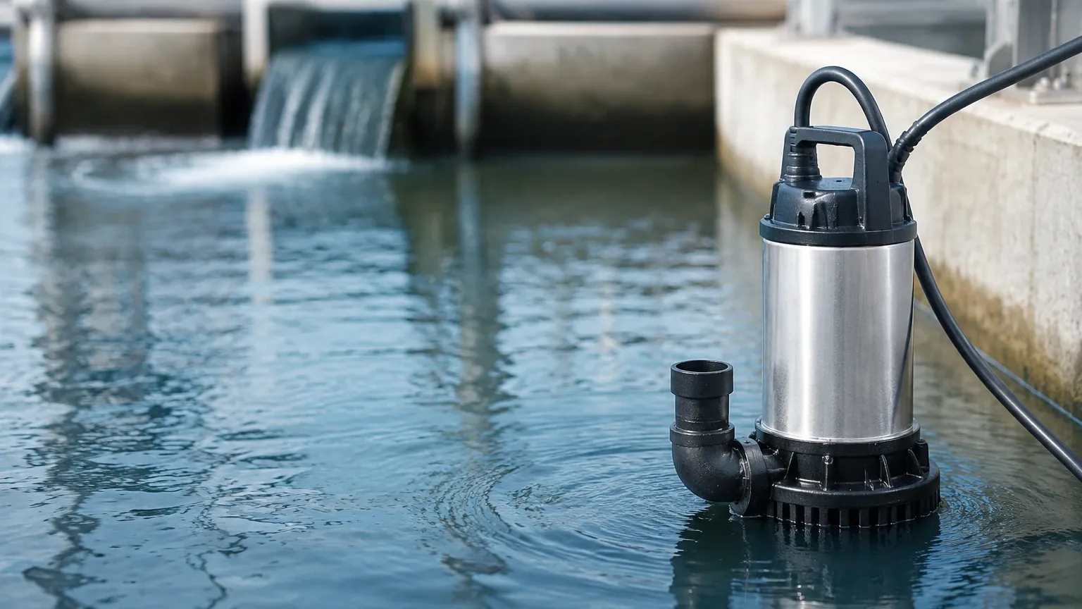
In industrial fluid management and wastewater treatment, the term "spump"—frequently used as a shorthand for sump pump systems or specialized slurry pump configurations—represents a critical node in process automation. These systems are designed to collect and move liquids from low-lying pits, basins, or tanks to higher elevations or treatment facilities. However, the mechanical reliability of a spump is only as effective as the level measurement technology controlling it. Without precise level monitoring, these systems face risks ranging from dry-running and motor burnout to hazardous overflows.
Selecting the correct level instrument for a spump application requires an understanding of the fluid dynamics within the pit, the presence of solids, and the environmental conditions such as foam, steam, or turbulence. This guide examines the core measurement principles and selection criteria necessary for optimizing industrial sump operations.
Principles of Level Measurement in Sump Applications
Before selecting a sensor for a spump system, it is essential to understand the physics behind the most common measurement technologies. Each method interacts differently with the liquid surface and the surrounding environment.
Ultrasonic Level Measurement
Ultrasonic sensors operate on the "time-of-flight" principle. The sensor emits a high-frequency sound pulse that travels through the air, reflects off the liquid surface, and returns to the transducer. By measuring the time taken for the pulse to return, the device calculates the distance to the liquid. This is a non-contact method, making it ideal for corrosive or dirty liquids typically found in industrial sumps. However, it can be affected by heavy foam or significant temperature fluctuations.
Radar Level Measurement (FMCW)
Frequency Modulated Continuous Wave (FMCW) radar, particularly at high frequencies like 80GHz, is the gold standard for challenging spump environments. Unlike ultrasonic waves, radar pulses are electromagnetic and do not require an air medium to travel. They are unaffected by steam, dust, or vacuum conditions. Radar provides high precision even in the presence of surface agitation or narrow pit geometries where side-wall reflections might interfere with other sensors.
Hydrostatic Pressure Measurement
This contact-based method involves placing a submersible pressure transmitter at the bottom of the sump. The sensor measures the pressure exerted by the liquid column above it. Since pressure is directly proportional to the height of the liquid (based on its specific gravity), the level can be determined accurately. This is often the most cost-effective solution for deep pits where mounting a top-down sensor is impractical.
Point Level Switches
While the above methods provide continuous monitoring, point level switches (such as float switches or tuning fork sensors) are used for discrete detection. In a spump setup, these are typically employed as redundant safety backups to trigger high-level alarms or to provide a hard-wired interlock to prevent the pump from running dry.
Technical Selection Criteria for Spump Systems
Choosing between these technologies depends on the specific characteristics of the media and the physical layout of the installation. The following table provides a comparison for engineering reference:
| Technology | Accuracy | Media Compatibility | Environmental Resistance | Ideal Use Case |
| :— | :— | :— | :— | :— |
| Ultrasonic | ±0.25% of range | Water, light chemicals | Moderate (Sensitive to foam) | Standard wastewater sumps |
| 80GHz Radar | ±1 mm to ±2 mm | Slurries, oils, acids | High (Ignores steam/vapor) | Chemical sumps with agitation |
| Hydrostatic | ±0.1% to ±0.5% | Clear liquids, grey water | High (Submerged) | Deep underground reservoirs |
| Float Switch | N/A (Point) | Most non-coating liquids | High (Mechanical) | Emergency high/low alarms |
When evaluating a Main Page for product specifications, engineers should prioritize sensors that offer a high Ingress Protection (IP) rating, typically IP68 for submersible components and IP67 for top-mounted electronics, to withstand the humid and often corrosive atmosphere of a pump pit.
Installation Considerations for Optimal Performance
The physical installation of a level sensor significantly impacts its long-term reliability. In a spump environment, several factors must be managed:
1. Dead Zones (Blocking Distance): All top-down sensors (ultrasonic and radar) have a "dead zone" immediately below the transducer face where measurements cannot be taken. The sensor must be mounted high enough so that the maximum liquid level never enters this zone.
2. Pump Intake Interference: Sensors should be positioned away from the pump's intake and discharge zones. Turbulence and vortices created by the pump can cause erratic readings or mechanical stress on submersible cables.
3. Obstructions: In narrow sumps, internal structures like ladders, pipes, or support beams can create false echoes. Using a radar sensor with a narrow beam angle (e.g., 3° to 6°) helps bypass these obstructions.
4. Stillwells: If the surface is excessively turbulent or covered in thick foam, installing the sensor inside a stillwell (a vertical pipe) can provide a calm surface for more accurate measurement. This is particularly useful for ultrasonic and floating-type sensors.
Limitations and Common Risks
Despite advancements in sensor technology, certain conditions can compromise the control of a spump system. Understanding these limitations is vital for risk mitigation.
Media Build-up and Fouling
In sumps handling slurries or wastewater with high fat/oil content, material can build up on the sensor face or the submersible diaphragm. This "coating" can lead to signal attenuation or false readings. Non-contact radar is generally more resistant to this, but even then, periodic cleaning may be required if the build-up becomes extreme.
Condensation and Steam
In hot-well sumps or chemical pits, condensation can form on the transducer face. While radar can penetrate thin layers of moisture, ultrasonic sensors may fail if water droplets block the transducer. Selecting a sensor with a PTFE (Teflon) face can help moisture shed more easily.
Chemical Compatibility
The housing and cable materials must be compatible with the liquid. For example, a hydrostatic sensor used in a chemical spump might require a PVDF housing and a FEP cable instead of standard stainless steel and PVC to prevent corrosion.
Maintenance and Calibration Guidance
To ensure the longevity of the level measurement system, a proactive maintenance schedule should be implemented. For contact-based sensors like hydrostatic transmitters, the diaphragm should be inspected every 6 to 12 months for signs of pitting or sediment accumulation. For non-contact sensors, a simple visual check of the antenna or transducer face is usually sufficient.
Calibration should be verified against a manual dip-tape measurement at least once a year. Most modern digital transmitters allow for remote calibration and diagnostics via HART or Modbus protocols, which reduces the need for technicians to enter confined sump spaces.
Frequently Asked Questions (FAQs)
Q: Can I use an ultrasonic sensor if there is foam in the sump?
A: Heavy, dense foam absorbs ultrasonic sound waves, often leading to a loss of signal. If foam is persistent, an 80GHz radar sensor or a hydrostatic pressure transmitter is a more reliable choice.
Q: How do I prevent my spump from running dry if the sensor fails?
A: It is best practice to install a redundant, low-level float switch wired directly to the pump's motor starter. This acts as a hardware-level safety that functions independently of the continuous level sensor and the PLC.
Q: What is the maximum depth for a hydrostatic level sensor?
A: Submersible sensors can typically handle depths up to 200 meters (approx. 656 feet), though most industrial spump applications rarely exceed 10 to 15 meters (33 to 49 feet).
Q: Does the specific gravity of the liquid affect radar measurements?
A: No. Radar measures the distance to the surface based on the dielectric constant of the material, not its weight or density. This makes radar highly effective for sumps where the liquid composition might change over time.
Conclusion
Effective management of a spump system relies on the seamless integration of mechanical pumping and electronic level sensing. By understanding the measurement principles of radar, ultrasonic, and hydrostatic technologies, engineers can select the most robust solution for their specific industrial environment. Proper installation, mindful of turbulence and obstructions, combined with a strategy for redundancy, ensures that the sump remains a reliable component of the facility's infrastructure. For those seeking detailed technical specifications and customized instrumentation, reviewing the options available through a professional manufacturer remains the most effective path toward system optimization.