Radar Level Transmitter Echo Curve
Radar Level Transmitter Echo Curve: A Technical Guide for Industrial Engineering
In the field of industrial process automation, non-contact level measurement has become the preferred standard for challenging environments involving corrosive chemicals, high temperatures, and volatile liquids. Among the various technologies available, Radar Level Meters stand out for their reliability and precision. However, the performance of these instruments is not merely a product of the hardware; it is deeply rooted in the interpretation of the radar level transmitter echo curve.
For instrumentation engineers and plant managers, understanding the echo curve is essential for commissioning, troubleshooting, and optimizing level measurement systems. This guide explores the measurement principles, the technical nuances of echo analysis, and the practical considerations for selecting and installing radar level transmitters.
Measurement Principles of Radar Level Technology
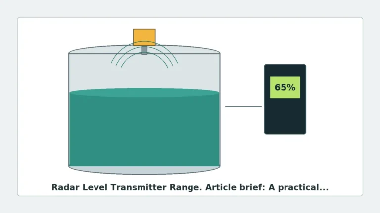
Radar level transmitters operate by emitting high-frequency electromagnetic waves (microwaves) toward the surface of a medium. These waves travel at the speed of light. When they encounter a change in the dielectric constant (the boundary between air and the product), a portion of the energy is reflected back to the sensor.
There are two primary methods used to calculate the level based on these reflections:
1. Pulse Radar (Time of Flight)
Pulse radar transmitters emit short microwave pulses. The instrument measures the time elapsed between the emission of the pulse and the reception of the reflected signal. Since the speed of light is constant, the distance ($D$) is calculated as:
$$D = \frac{c \times t}{2}$$
Where $c$ is the speed of light and $t$ is the measured time. The level is then derived by subtracting the distance from the total tank height.
2. FMCW (Frequency Modulated Continuous Wave)
FMCW radar transmits a continuous signal with a constantly changing frequency. The difference in frequency between the emitted signal and the reflected signal (the "beat frequency") is directly proportional to the distance. FMCW is generally more accurate than pulse radar and is the standard for high-precision applications, such as custody transfer.
Understanding the Radar Level Transmitter Echo Curve
The radar level transmitter echo curve is a graphical representation of the signal intensity (amplitude) returned to the sensor relative to the distance from the antenna. In a digital interface, the X-axis typically represents distance in meters (m), while the Y-axis represents signal strength in decibels (dB).
Key Components of the Echo Curve
* The Emission Pulse (Initial Peak): This is the signal seen at the very top of the curve, representing the energy leaving the antenna. The area immediately following this pulse is often referred to as the "dead zone" or "blocking distance," where the transmitter cannot accurately detect a return signal.
* The Surface Echo: This is the primary peak that the transmitter identifies as the material level. A sharp, high-amplitude peak indicates a clear reflection from a liquid surface with a high dielectric constant.
* The Noise Floor: This represents background electromagnetic interference and minor reflections from the tank atmosphere. A healthy system maintains a significant gap (Signal-to-Noise Ratio) between the surface echo and the noise floor.
* False Echoes: These are secondary peaks caused by internal tank structures such as agitators, heating coils, ladders, or weld seams. Advanced transmitters allow engineers to "map" these echoes, instructing the software to ignore them.
Technical Selection Criteria
Choosing the right radar transmitter requires matching the frequency and antenna design to the specific process conditions. The frequency of the radar signal significantly impacts the beam angle and the ability to penetrate foam or dust.
Comparison Table: Radar Frequency Bands
| Feature | 6 GHz (C-Band) | 26 GHz (K-Band) | 80 GHz (W-Band) |
| :— | :— | :— | :— |
| Beam Angle | Wide (approx. 20°–30°) | Medium (approx. 8°–12°) | Narrow (approx. 3°–4°) |
| Antenna Size | Large | Medium | Small/Compact |
| Dust/Steam Penetration | Excellent | Good | Moderate |
| Precision | ±10 mm (0.39 in) | ±3 mm (0.12 in) | ±1 mm (0.04 in) |
| Typical Application | Large outdoor basins, heavy turbulence | Standard process tanks, chemical storage | Narrow vessels, solids, high-precision liquids |
Installation Considerations and the Echo Curve
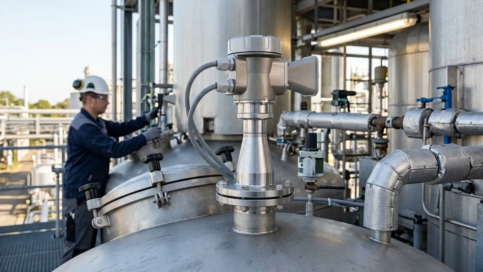
The physical installation of a radar level transmitter is the single most important factor in ensuring a clean radar level transmitter echo curve. Poor placement leads to signal attenuation and excessive false echoes.
1. Nozzle Geometry
The mounting nozzle should be as short and wide as possible. If a nozzle is too long or narrow, the radar signal may reflect off the internal walls of the nozzle, creating a large parasitic echo near the top of the tank that masks the true liquid level.
2. Obstruction Avoidance
The radar beam spreads as it travels. Any metallic object within the "beam cone" will reflect energy. Engineers must calculate the beam diameter at the bottom of the tank using the formula:
$$W = 2 \times D \times \tan(\frac{\alpha}{2})$$
Where $W$ is the beam diameter, $D$ is the distance, and $\alpha$ is the beam angle. If an agitator or pipe falls within this diameter, the transmitter must be relocated or the false echo must be suppressed via software.
3. Turbulence and Foam
Turbulent surfaces scatter the radar signal, resulting in a wider, lower-amplitude peak on the echo curve. Foam can be even more problematic; depending on its density and conductivity, it may either reflect the signal prematurely (measuring the top of the foam) or absorb the signal entirely, leading to a "loss of echo" error.
Application Risks and Limitations
While Radar Level Meters are highly versatile, they are subject to certain physical limitations:
* Dielectric Constant ($\epsilon_r$): The strength of the reflection depends on the dielectric constant of the medium. Non-polar liquids like oils and hydrocarbons have low $\epsilon_r$ values (1.4 to 2.0), resulting in weak echoes. Water-based liquids have high $\epsilon_r$ values (approx. 80) and provide very strong echoes.
* Condensation: Heavy condensation on the antenna can refract the radar signal or cause it to reflect off the moisture layer on the lens, leading to measurement drift. In such cases, antennas with PTFE covers or air purging systems are recommended.
* Vacuum and Pressure: While microwaves travel through a vacuum, high-pressure gases can slightly alter the propagation speed of the signal, requiring a correction factor for ultra-high-precision applications.
Troubleshooting with the Echo Curve
When a level transmitter provides an erratic reading, the echo curve is the primary diagnostic tool.
* Double Bounce: In some metallic tanks, the signal reflects off the liquid, then off the tank roof, then off the liquid again before returning to the sensor. This creates a "ghost" echo at exactly twice the actual distance.
* Echo Loss: If the curve shows only the noise floor with no distinct peak, the signal is likely being absorbed (by thick foam) or deflected away from the sensor (by a highly agitated or slanted surface).
* False Echo Suppression: Modern Welk instruments allow for "Empty Tank Mapping." By recording the echo curve of an empty vessel, the transmitter can identify all static reflections from internal structures and subtract them from the live signal, leaving only the reflection from the product surface.
Buyer’s Checklist: What to Confirm Before Ordering
To ensure the selected radar transmitter meets the requirements of an international industrial project, buyers should confirm the following data points with the manufacturer:
1. Medium Properties: What is the dielectric constant? Is the medium corrosive, or does it tend to coat surfaces?
2. Vessel Geometry: Provide the tank height, diameter, and the location of all internal obstructions.
3. Process Conditions: Maximum and minimum operating pressure and temperature. High temperatures may require a cooling extension for the electronics.
4. Output Requirements: Is a standard 4-20mA HART signal sufficient, or is a digital protocol like RS485 Modbus or Profibus required?
5. Hazardous Area Ratings: Does the installation site require ATEX, IECEx, or other explosion-proof certifications?
Frequently Asked Questions (FAQs)
Q: Can radar level transmitters measure solids?
A: Yes. However, solids typically have a lower dielectric constant and an angled surface (the angle of repose). 80GHz radar is usually preferred for solids due to its narrow beam and better signal processing capabilities.
Q: What is the difference between Guided Wave Radar (GWR) and Non-contact Radar?
A: GWR uses a physical probe (cable or rod) to guide the microwave signal. It is better for low-dielectric liquids and narrow bypass chambers. Non-contact radar (discussed here) emits signals through the air and is better for corrosive or viscous media that might cling to a probe.
Q: How often should the echo curve be checked?
A: During commissioning, a baseline echo curve should always be recorded. For critical processes, an annual review of the curve can help identify the buildup of material on the antenna or changes in the process that might affect measurement reliability.
Q: Does the tank material affect the radar signal?
A: Yes. Metallic tanks reflect all radar energy that doesn't hit the product, potentially creating more complex echo curves. Plastic or fiberglass tanks are "transparent" to radar; the signal can pass through the tank roof, allowing for measurement from outside the vessel in some specific low-frequency applications.
By focusing on the technical integrity of the radar level transmitter echo curve, engineers can ensure that their level measurement systems provide the accuracy and stability required for modern industrial automation. For more detailed specifications on equipment selection, users should consult professional technical resources and product documentation.