Radar Level Transmitter Endress Hauser PDF
Radar Level Transmitter Endress Hauser PDF
In the field of industrial process automation, the selection of instrumentation is a critical task that bridges the gap between theoretical design and operational reality. For engineers and procurement specialists, technical documentation—often searched for as a radar level transmitter endress hauser pdf—serves as the primary source of truth for integration. These documents contain the essential wiring diagrams, mounting dimensions, and signal processing logic required to ensure a successful installation.
Understanding the nuances of Radar Level Meters requires a deep dive into the physics of microwave propagation, the impact of dielectric constants, and the mechanical constraints of the vessel. This guide provides a comprehensive technical overview of radar level technology, focusing on the data points typically found in high-end industrial data sheets.
1. Measurement Principles: The Physics of Radar
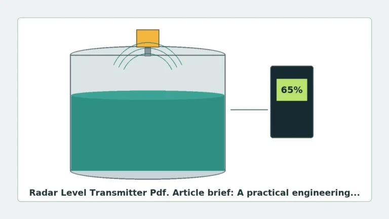
Radar level transmitters operate on the Time-of-Flight (ToF) principle. The device emits high-frequency electromagnetic waves (microwaves) toward the surface of the medium. These waves are reflected by the product surface and received by the antenna.
Pulse Radar vs. FMCW
There are two primary methods used in modern industrial radar transmitters to calculate the distance from the sensor to the material surface:
* Pulse Radar: The transmitter sends a microwave pulse and measures the time it takes for the pulse to travel to the surface and back. Because microwaves travel at the speed of light, the time intervals are extremely short (nanoseconds), requiring high-precision timing circuitry.
* FMCW (Frequency Modulated Continuous Wave): The transmitter emits a continuous signal with a constantly changing frequency. The frequency of the reflected signal is compared to the frequency of the signal being emitted at that moment. The difference between these frequencies (the "beat frequency") is directly proportional to the distance. FMCW is generally preferred for high-accuracy applications and is the standard for modern 80GHz transmitters.
The Role of the Dielectric Constant (εr)
The reliability of the radar reflection depends heavily on the dielectric constant of the medium. Materials with high dielectric constants (e.g., water, εr ≈ 80) reflect signals strongly. Materials with low dielectric constants (e.g., hydrocarbons, εr < 2.0) allow much of the signal to pass through, resulting in a weaker echo. When consulting a technical manual or a radar level transmitter endress hauser pdf, engineers must verify the minimum dielectric constant supported by the specific antenna configuration.
2. Frequency Bands and Their Applications
Industrial radar transmitters typically operate in three main frequency bands. Each has distinct advantages depending on the process environment.
| Frequency Band | Beam Angle | Typical Use Case | Advantages |
| :— | :— | :— | :— |
| 6 GHz (C-Band) | Wide (approx. 23°) | Heavy turbulence, steam, or foam. | Less affected by condensation or surface agitation. |
| 26 GHz (K-Band) | Medium (approx. 8-10°) | Standard liquid tanks, small vessels. | Good balance between beam focus and signal robustness. |
| 80 GHz (W-Band) | Narrow (approx. 3-4°) | Tall silos, vessels with internal obstructions. | Extremely focused beam; ignores nozzles and agitators. |
Why Beam Angle Matters
A narrow beam angle, characteristic of 80GHz technology, allows the sensor to avoid reflecting off tank walls, heating coils, or agitator blades. This simplifies the commissioning process, as there are fewer "false echoes" to mask in the software. In contrast, a wider 6GHz beam is more forgiving of heavy steam or dust, which might scatter a higher-frequency signal.
3. Interpreting Technical Documentation (PDFs)
When reviewing a radar level transmitter endress hauser pdf or any manufacturer's data sheet, several key technical parameters dictate the suitability of the device for a specific project.
Blocking Distance (Dead Zone)
Every radar sensor has a "blocking distance" near the antenna where measurement is not possible. Typically ranging from 50mm to 300mm, this must be accounted for in the vessel's overfill protection logic. If the liquid level enters the blocking distance, the device may report an error or hold the last valid value.
Signal-to-Noise Ratio (SNR)
The quality of the measurement is defined by the SNR. Modern digital signal processing (DSP) allows transmitters to filter out background noise caused by internal tank structures. Technical manuals often provide "echo curves," which are graphical representations of the returned signal strength over the measurement range. Analyzing these curves is essential for troubleshooting unstable readings.
Communication Protocols
Industrial integration requires compatibility with existing control systems. Most high-end Radar Level Meters support:
* 4-20mA HART: The industry standard for analog signals with digital superimposed data.
* Profibus PA / Foundation Fieldbus: For fully digital plant architectures.
* Modbus RTU: Often used in remote monitoring or oil and gas applications.
4. Installation and Mounting Considerations
Correct physical installation is the most significant factor in long-term reliability. Even the most advanced radar transmitter will fail if mounted improperly.
Nozzle Geometry
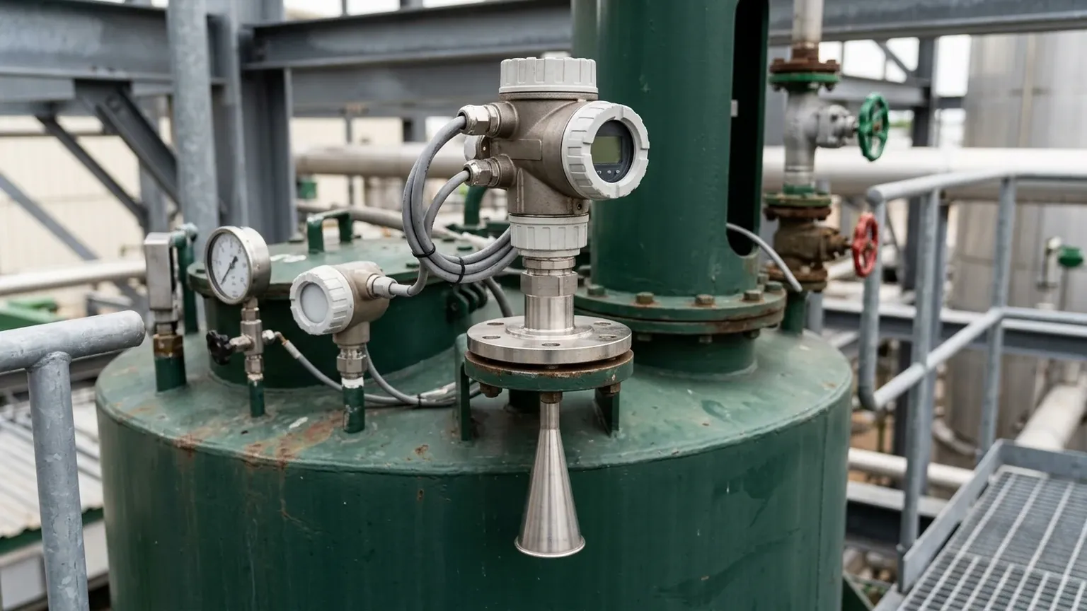
The mounting nozzle should be as short as possible. If the nozzle is too long or narrow, the radar signal may reflect off the internal edges of the pipe before it even enters the tank, creating a large "initial echo" that obscures the actual product level. For 80GHz units, nozzle interference is minimized, but for 26GHz units, the nozzle diameter should ideally be larger than the antenna diameter.
Position Relative to the Wall
Radar sensors should never be mounted in the center of a tank (to avoid multiple reflections from the tank dome) or too close to the wall. A common rule of thumb is to mount the sensor at 1/6th to 1/4th of the tank diameter from the wall. This ensures the beam has a clear path to the surface while avoiding the "whispering gallery" effect where signals crawl along the tank shell.
Obstruction Management
If an agitator or ladder is in the path of the signal, the transmitter's software can usually perform a "False Echo Suppression" or "Empty Tank Mapping." During commissioning, the engineer records the echoes of the empty tank, and the transmitter subsequently ignores these static reflections.
5. Limitations and Environmental Factors
While radar is often considered the "universal" level measurement solution, it does have physical limitations that must be addressed during the selection phase.
1. Heavy Foam: Dense, thick foam can absorb the microwave signal entirely, leading to a "Loss of Echo" (LoE) error. In these cases, a lower frequency (6GHz) or a guided wave radar (GWR) may be more appropriate.
2. Vacuum and Pressure: Unlike ultrasonic sensors, radar waves do not require a medium for propagation and work perfectly in a vacuum. However, high pressure can change the dielectric constant of the gas phase (e.g., high-pressure CO2), requiring a compensation factor in the distance calculation.
3. Condensation: Droplets on the antenna can refract the signal. Many modern Radar Level Meters utilize PTFE or PEEK drip-off antenna designs to shed condensation effectively.
6. Selection Table for Industrial Radar Transmitters
| Application | Recommended Technology | Key Reason |
| :— | :— | :— |
| Corrosive Chemicals | PTFE-encapsulated 80GHz | Chemical resistance and narrow beam for plastic tanks. |
| Large Grain Silos | 80GHz with Dust Purge | High frequency penetrates dust; narrow beam avoids wall drag. |
| Oil/Water Interface | Guided Wave Radar (GWR) | Through-air radar cannot reliably see the interface. |
| High-Pressure Steam | 6GHz or GWR | Lower frequencies are less attenuated by heavy vapor. |
| Hygienic/Food & Bev | Flush-mounted 80GHz | No crevices for bacterial growth; CIP/SIP compatible. |
7. Frequently Asked Questions (FAQ)
Q: Can I use a radar level transmitter for solids?
A: Yes, but the angle of repose must be considered. Solids reflect signals differently than liquids. 80GHz transmitters are generally preferred for solids due to their high signal sensitivity and ability to handle uneven surfaces.
Q: What is the difference between 2-wire and 4-wire transmitters?
A: 2-wire (loop-powered) devices receive power and transmit the signal over the same pair of wires, which is more cost-effective for installation. 4-wire devices have separate power supplies and are used when the sensor requires more power, such as for heated antennas or high-speed data processing.
Q: How do I find the specific register map for my device?
A: This information is typically found in the "Operating Instructions" or "Description of Device Parameters" section of the radar level transmitter endress hauser pdf or the manufacturer's technical manual. These maps are essential for PLC/SCADA integration via Modbus or Profibus.
Q: Does temperature affect radar accuracy?
A: Radar is largely unaffected by temperature changes in the headspace, unlike ultrasonic sensors which depend on the speed of sound. However, the electronics must be kept within their rated ambient temperature range, often -40°C to +80°C.
Conclusion
Selecting the right radar level transmitter involves more than just matching a range and an output signal. It requires a detailed analysis of the process chemistry, vessel geometry, and environmental conditions. By utilizing the technical data found in a radar level transmitter endress hauser pdf or similar engineering references, professionals can ensure they choose a device that provides high availability and low maintenance. Whether the application calls for the precision of 80GHz or the robustness of 6GHz, the fundamental goal remains the same: reliable, non-contact measurement that enhances process safety and efficiency.
Download Radar Level Transmitter Endress Hauser PDF as a PDF