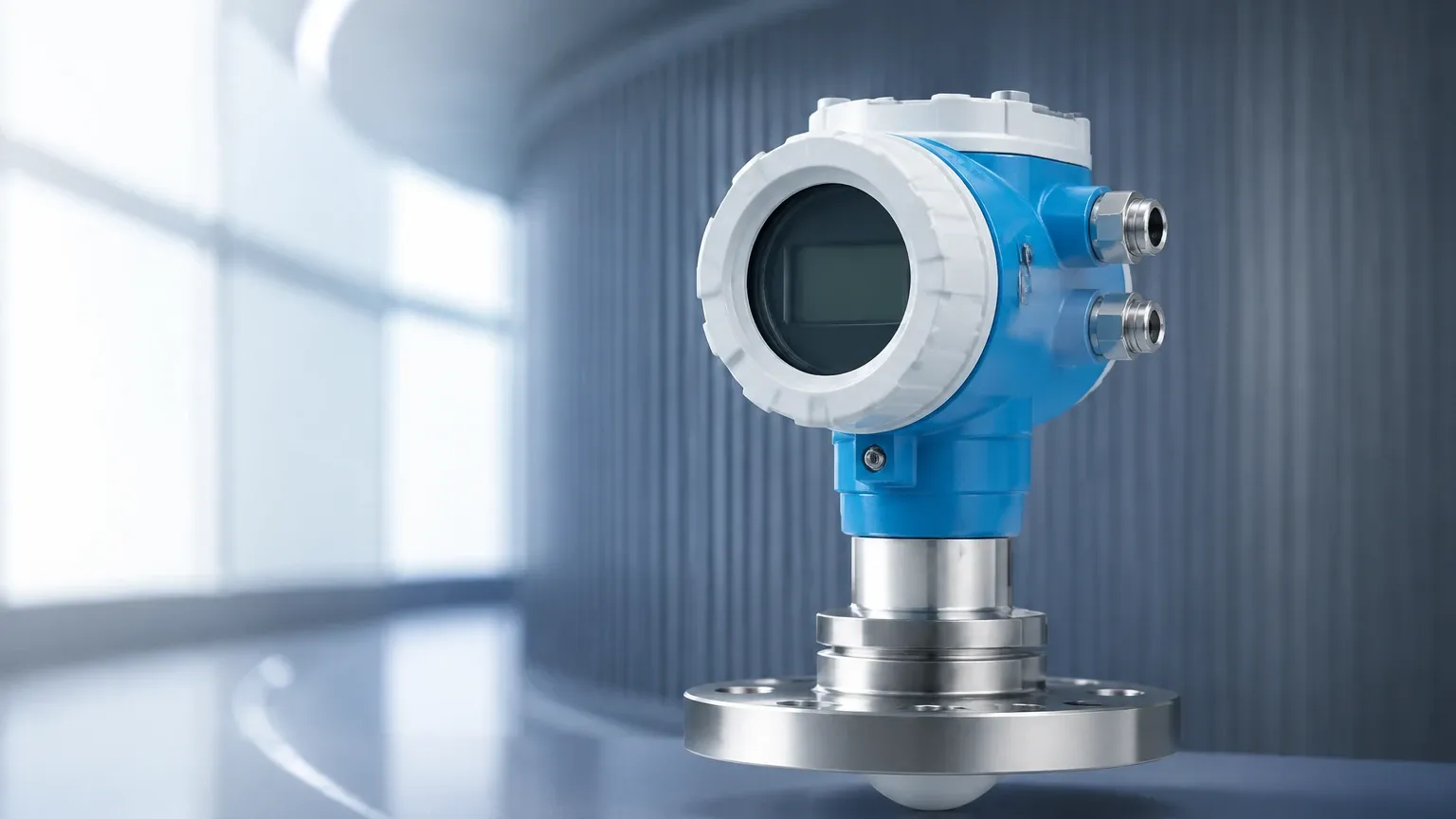
E&h Level Transmitter
E&h Level Transmitter
In the landscape of industrial process control, the level transmitter is a critical component for ensuring safety, efficiency, and inventory accuracy. Among the industry standards, the e&h level transmitter series is frequently cited by engineers as a benchmark for reliability in demanding environments. This guide provides a technical overview of the measurement principles, selection criteria, and installation considerations essential for professionals integrating these instruments into water treatment, chemical processing, and oil and gas applications.
Fundamental Measurement Principles for Industrial Level Sensors
Before selecting an e&h level transmitter or a comparable alternative, it is vital to understand the physics behind the measurement. Industrial level transmitters generally fall into two categories: contact and non-contact.
1. Radar Level Measurement (ToF)
Radar transmitters, specifically those operating on the Time-of-Flight (ToF) principle, emit high-frequency electromagnetic pulses. These pulses reflect off the surface of the medium and return to the sensor. The transmitter calculates the distance based on the time it takes for the pulse to travel to the surface and back.
Modern radar sensors often utilize Frequency Modulated Continuous Wave (FMCW) technology. In FMCW, the transmitter sends a continuous signal with a constantly changing frequency. The difference between the emitted and received frequency is proportional to the distance. High-frequency radar, such as 80GHz systems, offers a narrow beam angle, which is advantageous in narrow tanks with internal obstructions.
2. Ultrasonic Level Measurement
Ultrasonic sensors use sound waves rather than electromagnetic waves. A transducer emits an ultrasonic pulse that travels through the air, reflects off the liquid or solid surface, and returns. Because the speed of sound is affected by air temperature, these transmitters typically include an integrated temperature sensor to perform real-time compensation. Ultrasonic measurement is cost-effective but is limited by vacuum conditions (which cannot transmit sound) and heavy foam, which absorbs the acoustic signal.
3. Hydrostatic Pressure Measurement
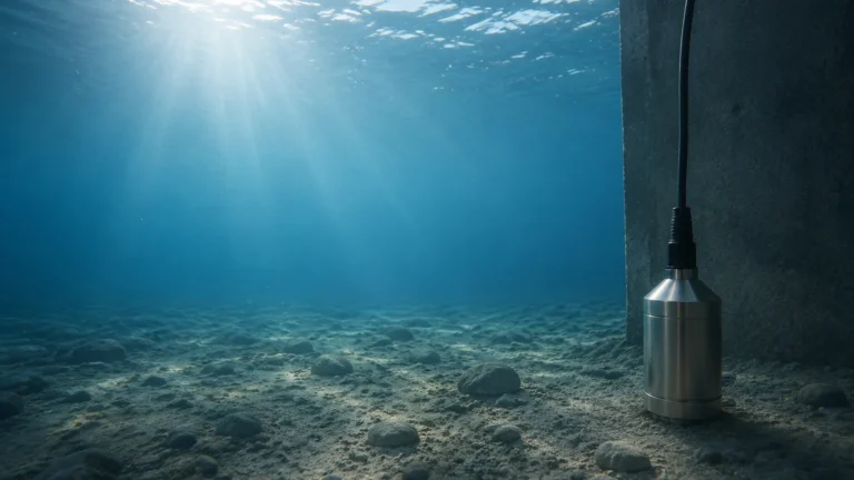
Hydrostatic transmitters measure the pressure exerted by a liquid column at a specific point. Based on the formula $P = \rho gh$ (where $P$ is pressure, $\rho$ is density, $g$ is gravity, and $h$ is height), the transmitter can determine the level if the density of the fluid is constant. This method is highly effective for vented tanks or deep wells, often utilizing submersible probes or flange-mounted diaphragm seals.
4. Guided Wave Radar (GWR)
Guided Wave Radar uses a physical probe (rod or cable) to guide the microwave pulse to the surface. This technology is less affected by surface turbulence, foam, or changing vapors in the headspace, making it a robust choice for complex chemical interfaces.
Key Evaluation Criteria for Selecting a Level Transmitter
Choosing the right e&h level transmitter—or evaluating an equivalent from the Main Page of a specialized manufacturer—requires a detailed analysis of the process environment.
Media Characteristics
* Dielectric Constant ($ε_r$): For radar measurement, the reflectivity of the medium depends on its dielectric constant. Water has a high $ε_r$ (~80), making it easy to detect, while hydrocarbons have low $ε_r$ values (~1.9 to 2.5), which may require more sensitive electronics or Guided Wave Radar.
* Corrosiveness: The wetted parts must be compatible with the media. Common materials include 316L Stainless Steel, Hastelloy, and plastics like PVDF or PTFE for aggressive acids.
* Viscosity and Coating: If the medium is prone to buildup, non-contact radar or ultrasonic sensors are preferred over contact probes to reduce maintenance.
Process Conditions
* Temperature and Pressure: Standard sensors may operate up to 80°C (176°F), but high-temperature versions can withstand over 400°C (752°F). Similarly, pressure ratings must be checked for pressurized reactors.
* Turbulence and Foam: Rapidly mixing liquids or those producing thick foam can scatter signals. In these cases, GWR or hydrostatic transmitters often provide more stable readings than free-space radar.
Practical Technology Selection and Comparison
The following table summarizes the typical application ranges and performance metrics for common level measurement technologies used in industrial automation.
| Technology | Typical Range | Accuracy | Ideal Media | Limitations |
| :— | :— | :— | :— | :— |
| Free-space Radar | 0.3m to 120m | ±1mm to ±5mm | Liquids, Solids, Slurries | Low dielectric liquids |
| Ultrasonic | 0.2m to 15m | ±0.25% of range | Water, Wastewater | Foam, Vacuum, High Dust |
| Hydrostatic | 1m to 200m | ±0.1% to ±0.5% | Clear liquids, Oils | Changing fluid density |
| Guided Wave Radar| 0.3m to 45m | ±2mm | Chemicals, Interfaces | Mechanical probe interference |
Installation Best Practices for Accurate Measurement
Even the highest quality e&h level transmitter will fail to provide accurate data if installed incorrectly. Engineering teams should adhere to these fundamental guidelines:
1. Nozzle Dimensions: For radar and ultrasonic sensors, the nozzle height and diameter must not interfere with the signal beam. The sensor should ideally protrude slightly into the tank or be mounted in a nozzle that meets the manufacturer's "blocking distance" requirements.
2. Avoid Obstructions: Sensors should be positioned away from ladders, heating coils, and agitators. If obstructions are unavoidable, many modern transmitters offer "false echo suppression" software to map out and ignore these static reflections.
3. Inflow Streams: Never install a level sensor directly above the filling point. The turbulence and the falling stream will cause erratic readings and potential signal loss.
4. Grounding and Shielding: Industrial environments are rife with electromagnetic interference (EMI). Ensure the transmitter housing is properly grounded and that signal cables are shielded, especially when using 4-20mA HART or Modbus communication protocols.
5. Venting for Hydrostatic Probes: When using submersible hydrostatic transmitters, the reference capillary in the cable must be kept clear and protected from moisture to ensure accurate atmospheric pressure compensation.
Limitations and Common Application Risks
Understanding where a technology might fail is as important as knowing where it succeeds.
* The "Dead Band" (Blocking Distance): Every ToF sensor has a minimum distance near the sensor face where it cannot measure. If the tank overfills into this zone, the transmitter may report a "lost signal" or hold the last known value, which can lead to tank overflows.
* Gas Stratification: In large outdoor tanks, temperature gradients in the air/gas space can cause sound waves (ultrasonic) to refract, leading to inaccuracies. Radar is generally immune to these gas-phase changes.
* Signal Attenuation in Solids: Measuring the level of grain, plastic pellets, or ores involves irregular surfaces that scatter signals. High-power radar with specialized algorithms for "solids tracking" is necessary for these applications.
* Condensation and Buildup: Moisture on an ultrasonic transducer face can prevent the crystal from vibrating. Many radar units now use PTFE drip-off antennas to shed condensation and maintain signal integrity.
Frequently Asked Questions (FAQ)
Q: Can an e&h level transmitter be used for interface measurement?
A: Yes, Guided Wave Radar (GWR) is the primary technology for interface measurement (e.g., oil over water). It detects the first reflection from the upper medium and a second reflection from the lower, more conductive medium.
Q: How often should these transmitters be calibrated?
A: While many modern digital transmitters have low drift, annual verification is a standard practice in regulated industries like water treatment or pharmaceuticals. Hydrostatic sensors may require more frequent checks if the fluid density varies seasonally.
Q: What is the advantage of 80GHz radar over 26GHz radar?
A: The 80GHz frequency allows for a much smaller antenna and a narrower beam (often as tight as 3 degrees). This makes it easier to install in small tanks or tanks with many internal pipes, as the beam can "miss" these obstructions more easily.
Q: Is it possible to replace an e&h level transmitter with a different brand?
A: Yes. As long as the process connection (flange or thread), output signal (typically 4-20mA HART), and material compatibility match, instruments from specialized manufacturers can be used. For those looking to optimize their equipment budget without sacrificing accuracy, reviewing options on the Main Page can yield highly compatible solutions for most industrial applications.
Conclusion
Successful level measurement depends on matching the physics of the sensor to the characteristics of the process. Whether deploying an e&h level transmitter for a high-pressure reactor or an ultrasonic sensor for a simple water sump, engineers must prioritize chemical compatibility, the impact of the tank's internal geometry, and the specific limitations of the chosen technology. By following rigorous selection and installation standards, facilities can ensure long-term operational safety and data reliability.