Temperature Transmitter Rtd
Temperature Transmitter Rtd
In the landscape of industrial process control, the accurate measurement of temperature is as fundamental as the measurement of pressure or flow. Among the various technologies available, the Resistance Temperature Detector (RTD) paired with a dedicated transmitter stands out for its stability and precision. For engineers and technicians managing complex systems—ranging from chemical reactors to large-scale storage tanks—understanding the synergy between a temperature transmitter and an RTD is essential for maintaining process integrity and safety.
While primary focus often rests on level measurement technologies, such as those found on the Main Page of industrial instrumentation catalogs, temperature remains a critical secondary variable. It directly impacts fluid density, vapor pressure, and material expansion, all of which are vital for accurate level and volume calculations.
Measurement Principles: How RTDs and Transmitters Work
To effectively deploy a temperature transmitter RTD system, one must first understand the physics governing the sensor and the electronics that interpret its signal.
The RTD Sensor Principle
An RTD operates on the principle that the electrical resistance of a metal increases as its temperature rises. This phenomenon is known as the Temperature Coefficient of Resistance (TCR). Most industrial RTDs are constructed from platinum due to its linear relationship between resistance and temperature, as well as its chemical inertness. The most common type is the Pt100, which has a resistance of 100 ohms at 0°C (32°F). Pt1000 sensors, offering 1000 ohms at 0°C, are also used in applications where higher sensitivity or lower power consumption is required.
The Role of the Transmitter
The temperature transmitter serves as the bridge between the raw resistance signal of the RTD and the control system (PLC or DCS). An RTD’s resistance change is relatively small, and sending this raw signal over long distances can result in significant errors due to lead wire resistance and electromagnetic interference (EMI).
The transmitter performs several critical functions:
1. Signal Conversion: It converts the ohmic resistance into a standardized industrial signal, typically 4-20 mA, HART, or a digital fieldbus protocol.
2. Linearization: While platinum RTDs are fairly linear, the transmitter applies mathematical corrections to ensure the output signal perfectly matches the temperature curve.
3. Isolation: It protects the control system from electrical surges and ground loops.
4. Scaling: It allows the user to define the specific temperature range (e.g., -50°C to +200°C) that corresponds to the 4-20 mA output.
The Intersection of Temperature and Level Measurement
In many B2B industrial applications, temperature measurement is not an isolated requirement but a necessary component of accurate level sensing. For instance, in hydrostatic level measurement, the transmitter measures the pressure exerted by a liquid column. However, because liquid density changes with temperature, a hydrostatic level reading can become inaccurate if the temperature fluctuates. By integrating a temperature transmitter RTD into the system, the control logic can dynamically compensate for density changes, ensuring precise inventory management.
Similarly, in high-precision radar level applications, temperature monitoring of the tank headspace or the liquid surface helps in identifying potential condensation issues or boiling points that might affect signal propagation.
Technical Selection Criteria
Choosing the right temperature transmitter RTD configuration requires an evaluation of the specific process environment and the required accuracy levels.
Wiring Configurations
RTDs are typically available in 2-wire, 3-wire, or 4-wire configurations. The choice of wiring significantly impacts the accuracy of the transmitter's output:
* 2-Wire: The simplest and least expensive. However, the transmitter cannot distinguish between the resistance of the sensor and the resistance of the lead wires. This leads to an offset error that increases with wire length.
* 3-Wire: The industry standard for most industrial applications. It uses a third wire to measure and subtract the lead wire resistance, assuming all three wires have identical resistance.
* 4-Wire: The most accurate configuration. It uses a pair of wires to carry the excitation current and a separate pair to measure the voltage drop across the RTD, completely eliminating the effect of lead wire resistance.
Transmitter Mounting Styles
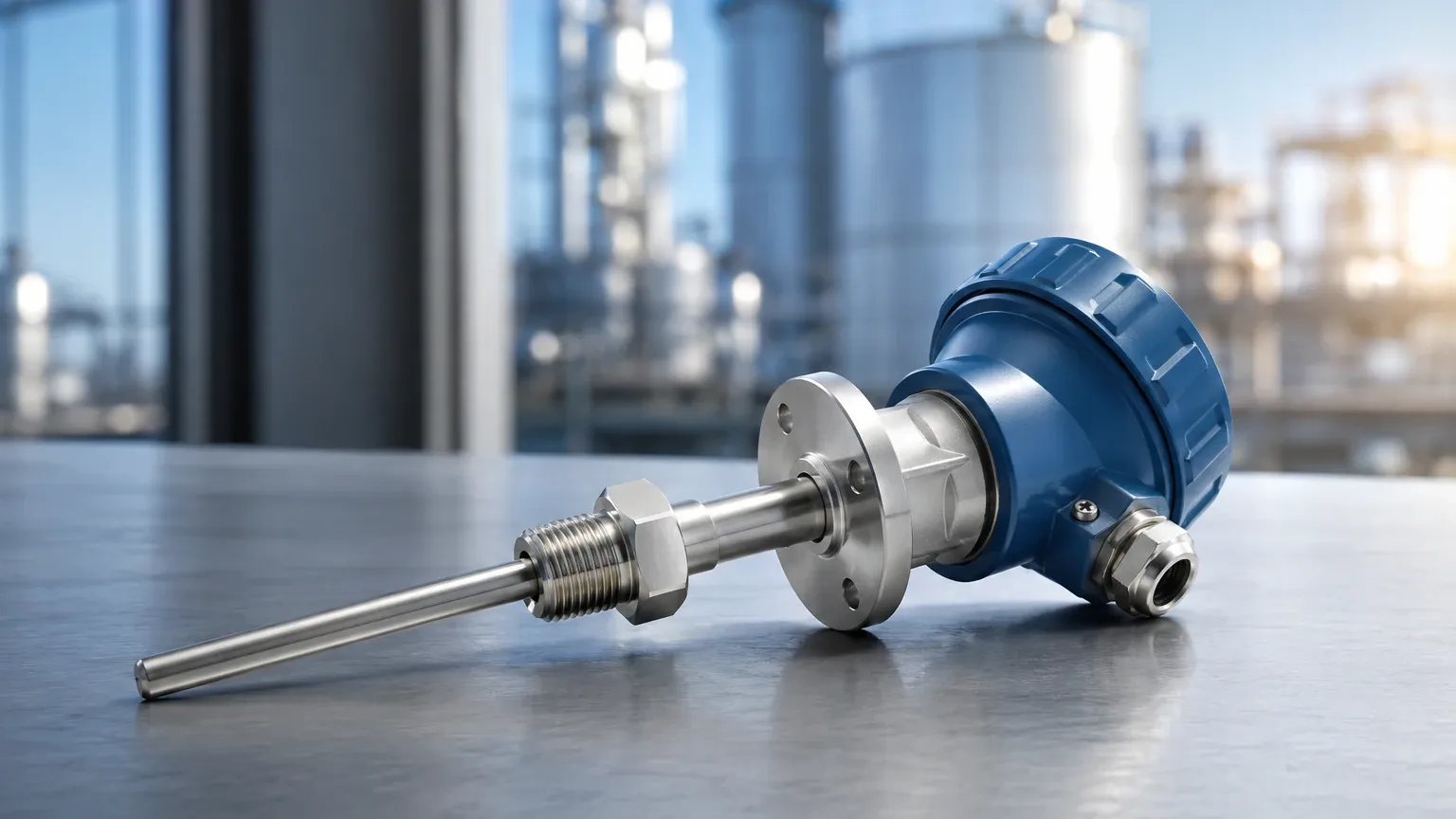
* Head-Mount: The transmitter is installed directly inside the connection head of the RTD sensor probe. This minimizes the distance the raw resistance signal travels, reducing noise.
* DIN Rail Mount: Located in a remote control cabinet. This is preferred when the sensor is located in an environment with extreme vibration or heat that might damage the transmitter electronics.
* Field-Mount: Housed in a rugged, explosion-proof, or weather-proof enclosure, often with a local display. These are used in harsh outdoor or hazardous area environments.
Practical Selection Table
| Feature | Pt100 RTD | Pt1000 RTD | Thermocouple (Comparison) |
| :— | :— | :— | :— |
| Temperature Range | -200°C to +850°C | -200°C to +600°C | -270°C to +2300°C |
| Accuracy | Very High | High | Moderate |
| Stability | Excellent | Excellent | Fair |
| Linearity | High | High | Low |
| Transmitter Cost | Moderate | Moderate | Lower |
| Best Use Case | Precision industrial processes | Battery-powered/Low-power | High-heat furnaces |
Installation Considerations
Proper installation is paramount to ensuring the longevity and accuracy of a temperature transmitter RTD assembly.
Thermowell Integration
In most industrial processes, the RTD probe is not inserted directly into the fluid. Instead, it is placed inside a thermowell—a pressure-tight receptacle. While the thermowell protects the sensor from corrosion and high flow velocities, it introduces a thermal lag. To minimize this, the gap between the RTD sensor tip and the thermowell bottom should be filled with a thermal conductive paste, or a spring-loaded sensor design should be used to ensure constant contact.
Environmental Protection
Transmitters must be rated for the environment in which they operate. In chemical processing or offshore oil and gas applications, stainless steel housings and IP67/IP68 ingress protection are standard. If the installation is in a zone with explosive gases, the transmitter must be certified as Intrinsically Safe (IS) or Explosion-Proof (XP).
Lead Wire Compensation
Even with a 3-wire transmitter, ensure that the lead wires are of the same gauge and length. Variations in wire resistance between the three leads will result in measurement drift. For distances exceeding 100 meters (approx. 328 feet), upgrading to a 4-wire system or moving the transmitter to a head-mount position is highly recommended.
Limitations and Potential Risks
While RTDs are highly reliable, they are not without limitations:
1. Self-Heating: The transmitter must pass a small current through the RTD to measure resistance. This current generates a tiny amount of heat. If the current is too high or the process medium is not circulating well, the sensor may report a temperature slightly higher than the actual process temperature.
2. Vibration: The fine platinum wire inside an RTD can be fragile. In high-vibration environments, such as near large pumps or compressors, thin-film RTDs or specially ruggedized wire-wound sensors should be specified.
3. Response Time: Compared to thermocouples, RTDs generally have a slower response time to rapid temperature changes, especially when encased in heavy-duty thermowells.
Frequently Asked Questions (FAQ)
Q: Can I use a temperature transmitter with any RTD?
A: Most modern universal temperature transmitters can be configured for Pt100, Pt500, or Pt1000 sensors. However, you must ensure the transmitter's input configuration matches the sensor's wiring (e.g., setting the transmitter to "3-wire" mode).
Q: How often should a temperature transmitter RTD be calibrated?
A: In critical B2B process industries, annual calibration is standard. RTDs are known for their low drift (typically less than 0.1°C per year), but the transmitter electronics should be verified against a known resistance standard to ensure the 4-20 mA loop remains accurate.
Q: What is the difference between a Class A and Class B RTD?
A: This refers to the tolerance of the sensor. A Class A Pt100 RTD has an accuracy of ±(0.15 + 0.002|t|)°C, while Class B is ±(0.30 + 0.005|t|)°C. For most industrial transmitter applications, Class A is preferred for its tighter precision.
Q: Why use a 4-20 mA transmitter instead of wiring the RTD directly to the PLC?
A: Wiring directly requires specialized RTD input cards at the PLC, which are expensive. Furthermore, the long runs of copper wire required to reach a central control room introduce significant resistance errors and noise. A transmitter converts the signal at the source, allowing the use of standard, inexpensive twisted-pair cabling over long distances without signal degradation.
Conclusion
The temperature transmitter RTD is a cornerstone of modern industrial instrumentation. By converting a sensitive resistance measurement into a robust industrial signal, these devices provide the data necessary for safety, efficiency, and quality control. Whether used for direct process monitoring or as a compensation tool for level measurement systems, understanding the nuances of RTD selection and transmitter configuration is vital for any engineering project.
For those seeking comprehensive solutions in industrial automation, exploring the various measurement technologies available on the Main Page can provide further insight into how temperature, level, and pressure instruments work together to optimize process performance. By adhering to strict installation guidelines and selecting the appropriate wiring and mounting configurations, operators can ensure their temperature measurement systems provide reliable service for years to come.