Temperature Transmitters
Temperature Transmitters
In the landscape of industrial process control, temperature is the most frequently measured physical parameter. However, the raw signals generated by primary temperature sensors, such as Resistance Temperature Detectors (RTDs) and Thermocouples, are often weak, non-linear, and susceptible to electromagnetic interference over long distances. This is where temperature transmitters become indispensable. A temperature transmitter is an electrical instrument that interfaces with a temperature sensor to isolate, amplify, filter noise, linearize, and convert the sensor signal into a standardized industrial output signal, typically 4-20 mA or a digital fieldbus protocol.
For engineers and plant operators, selecting the right temperature transmitters is not merely about measuring heat; it is about ensuring the integrity of the data that drives automated systems. This guide explores the technical principles, selection criteria, and the critical role these devices play in integrated process environments, including their relationship with level measurement systems found on our Main Page.
Measurement Principles and Signal Conversion
Before selecting a transmitter, it is vital to understand the physics of the sensors they support. Temperature transmitters primarily interface with two types of sensors: RTDs and Thermocouples.
Resistance Temperature Detectors (RTDs)
RTDs operate on the principle that the electrical resistance of a metal increases as its temperature rises (Positive Temperature Coefficient). The most common industrial RTD is the Pt100, which has a resistance of 100 Ohms at 0°C. The transmitter measures this resistance by passing a small, constant current through the sensor and measuring the voltage drop. Modern transmitters are designed to compensate for lead-wire resistance using 3-wire or 4-wire configurations, ensuring that the resistance of the cables does not skew the temperature reading.
Thermocouples
Thermocouples consist of two dissimilar metal wires joined at one end (the sensing junction). When there is a temperature gradient between the sensing junction and the reference junction (the transmitter terminals), a small voltage in the millivolt (mV) range is generated due to the Seebeck effect. The transmitter must perform two critical tasks for thermocouples: Cold Junction Compensation (CJC) to account for the temperature at the transmitter terminals and linearization of the non-linear mV-to-temperature relationship characteristic of different thermocouple types (e.g., Type K, J, or T).
The Transmitter’s Role
Once the raw signal is received, the transmitter performs signal conditioning. This includes:
1. Isolation: Protecting the control system from ground loops and high-voltage transients.
2. Linearization: Converting the non-linear sensor curve into a linear 4-20 mA output proportional to the temperature range.
3. Standardization: Outputting a signal that can travel hundreds of meters to a PLC or DCS without significant degradation.
The Critical Link Between Temperature and Level Measurement
In many industrial applications, temperature measurement is a prerequisite for accurate level measurement. Temperature transmitters are often deployed alongside level sensors to provide compensation data.
Hydrostatic Level and Density
Hydrostatic level transmitters calculate the height of a liquid based on the pressure exerted by the liquid column. Because the density of a liquid changes with temperature, a fixed pressure reading could represent different levels at different temperatures. By integrating data from temperature transmitters, the control system can calculate the corrected density and provide an accurate level reading.
Ultrasonic Level and the Speed of Sound
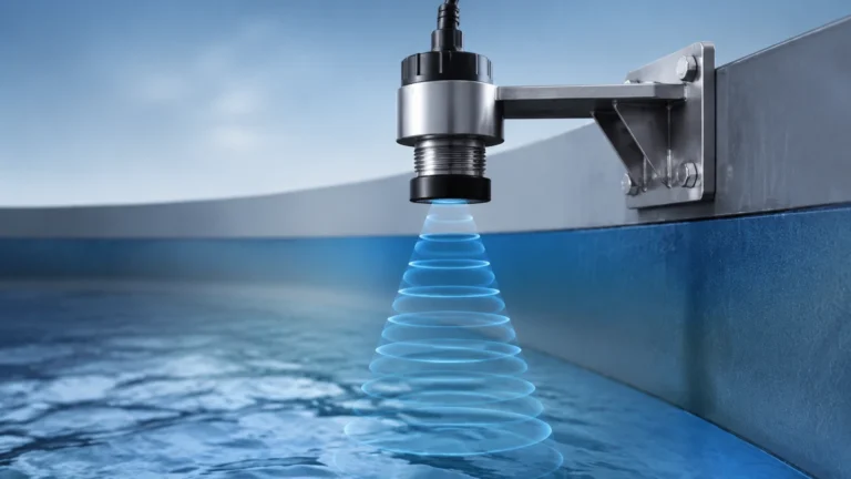
Ultrasonic level sensors measure the time it takes for a sound wave to travel to the liquid surface and back. The speed of sound in air (or a gas buffer) is highly dependent on temperature. A change of just 1°C can result in a measurement error if not compensated. Most high-quality ultrasonic systems utilize an integrated or external temperature transmitter to adjust the calculation in real-time.
Radar and Dielectric Constants
While radar level meters are less sensitive to temperature than ultrasonic sensors, extreme temperature fluctuations can still affect the dielectric constant of certain fluids or the mechanical integrity of the tank. Monitoring these conditions ensures the long-term reliability of the level measurement solution. For more information on integrated level and temperature solutions, visit our Main Page.
Types of Temperature Transmitter Configurations
Temperature transmitters are categorized by their physical form factor and mounting style. The choice depends on the accessibility of the measurement point and the environmental conditions.
| Type | Mounting Location | Pros | Cons |
| :— | :— | :— | :— |
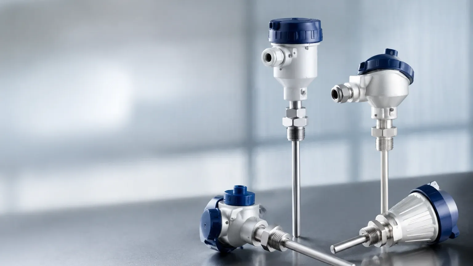
| Head-Mount | Inside the sensor connection head (DIN Form B). | Compact, eliminates long lead-wire runs, cost-effective. | Difficult to access for maintenance in high-heat or vibrating areas. |
| DIN Rail Mount | Inside a control cabinet or junction box. | Easy access for calibration, protected from the elements. | Requires long runs of sensor-grade wire (extension wire), prone to noise. |
| Field-Mount | In a dedicated ruggedized enclosure near the sensor. | Best protection for harsh environments, often includes local displays. | Higher initial cost, requires more space. |
Technical Selection Criteria
When evaluating temperature transmitters for a specific project, consider the following technical parameters:
1. Input Versatility: Does the transmitter support both RTDs and multiple thermocouple types? Universal transmitters offer the most flexibility for spare parts management.
2. Accuracy and Stability: Look for low "temperature drift" specifications. Industrial-grade transmitters should maintain accuracy even when the ambient temperature at the transmitter itself changes.
3. Output Protocol: While 4-20 mA is standard, many modern plants require HART (Highway Addressable Remote Transducer) protocol, which allows for digital diagnostics and remote configuration over the same two wires.
4. Galvanic Isolation: High isolation (e.g., 2000V AC) is essential in environments with high electrical noise or where sensors are grounded at the process point.
5. Hazardous Area Certifications: For oil, gas, or chemical applications, ensure the transmitter carries the necessary ATEX, IECEx, or UL intrinsic safety ratings.
Installation and Maintenance Guidelines
Proper installation is critical to the longevity of temperature transmitters and the accuracy of the process data.
Thermowell Considerations
In most industrial processes, the sensor is not placed directly in the fluid. Instead, it is inserted into a thermowell—a pressure-tight receptacle. The transmitter must be configured to account for the thermal lag introduced by the thermowell. Using a thermal transfer compound can improve response times.
Wiring and Grounding
To prevent Electromagnetic Interference (EMI), use shielded twisted-pair cabling for the 4-20 mA loop. The shield should be grounded at only one end (usually the control room side) to avoid ground loops. For RTDs, 3-wire or 4-wire connections are preferred to automatically cancel out the resistance of the lead wires.
Calibration
Transmitters should be calibrated periodically. This typically involves using a dry-block calibrator or a precision signal simulator to verify that the transmitter correctly converts the sensor input to the expected output. Smart transmitters with HART protocol can often be calibrated and diagnosed without removing them from the field.
Common Risks and Limitations
Despite their reliability, temperature transmitters are subject to certain risks:
* Ambient Temperature Limits: Transmitters have their own operating temperature range (typically -40°C to +85°C). If the process heat radiates into the connection head and exceeds this limit, the electronics may fail or drift significantly.
* Sensor Burnout: If a sensor fails (open circuit), the transmitter must be configured to "fail-high" (e.g., 21.5 mA) or "fail-low" (e.g., 3.6 mA) so the control system can trigger an alarm.
* Vibration: In applications with heavy machinery, vibration can cause mechanical failure of the transmitter electronics or the sensor connections. In these cases, remote DIN rail mounting is preferred.
Frequently Asked Questions (FAQ)
Q: Can I use a temperature transmitter with any sensor?
A: Most modern "universal" transmitters support a wide range of RTDs (Pt100, Pt500, Pt1000) and Thermocouples (J, K, T, E, R, S, B, N). However, you must always verify the input compatibility in the manufacturer's datasheet.
Q: Why use a transmitter instead of wiring the sensor directly to the PLC?
A: Wiring a thermocouple directly to a PLC requires expensive thermocouple extension wire and is highly susceptible to noise. A transmitter converts the signal to 4-20 mA, which is robust, uses standard copper wire, and allows for much longer distances.
Q: What is the benefit of a HART-enabled transmitter?
A: HART allows you to read digital diagnostics, such as sensor health or internal device temperature, while the 4-20 mA signal continues to provide the primary process variable. It also simplifies configuration via a handheld communicator or PC software.
Q: How does ambient temperature affect the transmitter?
A: All electronic components are affected by heat. High-quality transmitters specify a "temperature coefficient," which tells you how much the accuracy will change for every degree the ambient temperature fluctuates from the calibration point (usually 20°C or 25°C).
Conclusion
Selecting and installing the correct temperature transmitters is a foundational step in building a reliable industrial control system. Whether used for direct process monitoring or as a compensation tool for level measurement, these devices ensure that thermal data is accurate, stable, and protected from environmental interference. By understanding the measurement principles and matching the transmitter configuration to the specific needs of the application, engineers can significantly reduce measurement errors and maintenance costs. For a comprehensive range of instrumentation solutions, including those for complex level and temperature applications, explore the resources available on our Main Page.