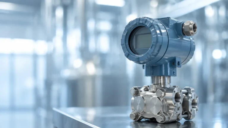
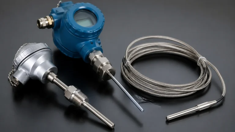
Prosonic Flow Meter
Prosonic Flow Meter
In the landscape of industrial automation and process control, the accurate measurement of fluid movement is as critical as monitoring the volume within a vessel. The prosonic flow meter represents a sophisticated class of ultrasonic measurement technology designed to provide high-precision data without necessarily coming into contact with the process medium. For engineers and facility managers, understanding the nuances of ultrasonic flow measurement is essential for optimizing system efficiency, ensuring safety, and maintaining regulatory compliance across diverse sectors such as water treatment, chemical processing, and oil and gas.
While level measurement instruments—such as those provided on the Welk Main Page—focus on the vertical height of substances, flow meters address the velocity and volume of fluids in motion. Often, these two measurement types are integrated into a single process control loop to provide a comprehensive view of material balance within a plant.
Measurement Principles of Ultrasonic Flow Meters
The prosonic flow meter operates primarily on two distinct ultrasonic principles: Transit-Time and the Doppler Effect. Selecting the correct principle depends entirely on the characteristics of the fluid being measured.
Transit-Time Difference Principle
This is the most common method used for clean liquids. The system utilizes two transducers, typically mounted on opposite sides of a pipe. Both transducers act as both transmitters and receivers. One transducer sends an ultrasonic signal diagonally across the pipe to the other.
When the fluid is stationary, the time taken for the signal to travel from A to B is identical to the time from B to A. However, when the fluid is moving, the signal traveling with the flow moves faster, and the signal traveling against the flow moves slower. The difference in these transit times is directly proportional to the flow velocity. The meter then calculates the volumetric flow rate based on the pipe's cross-sectional area.
Doppler Effect Principle
The Doppler principle is utilized when the fluid contains suspended solids, gas bubbles, or high turbidity. The transducer emits an ultrasonic signal into the pipe. This signal reflects off the moving particles or bubbles within the liquid. Because the particles are moving, the frequency of the reflected signal is shifted (the Doppler shift). By measuring this frequency change, the prosonic flow meter determines the velocity of the particles, and by extension, the velocity of the fluid.
Comparison of Ultrasonic Flow Technologies
To assist in the selection process, the following table outlines the differences between the primary ultrasonic methods and their typical application environments.
| Feature | Transit-Time Ultrasonic | Doppler Ultrasonic |
| :— | :— | :— |
| Best Fluid Type | Clean liquids, low turbidity | Slurries, aerated liquids, high solids |
| Typical Accuracy | ±0.5% to ±1% of rate | ±2% to ±5% of rate |
| Pipe Sizes | 15 mm to 4000 mm | 25 mm to 3000 mm |
| Installation Type | Inline or Clamp-on | Primarily Clamp-on |
| Major Limitation | Sensitive to bubbles/solids | Requires minimum particle concentration |
| Maintenance | Very low (no moving parts) | Very low |
Key Selection Criteria for Industrial Applications
When evaluating a prosonic flow meter for a specific project, several technical factors must be confirmed to ensure reliable performance.
1. Fluid Characteristics
The presence of entrained air or suspended solids is the primary determinant. If the liquid is ultra-pure water or refined chemicals, transit-time is the standard. If the application involves wastewater sludge or mining slurries, Doppler technology is required. It is also important to note the fluid's sound conductivity; some specialized hydrocarbons may require specific transducer frequencies.
2. Pipe Material and Condition
For clamp-on versions of the prosonic flow meter, the ultrasonic signal must pass through the pipe wall. Materials like carbon steel, stainless steel, and most plastics are excellent conductors. However, pipes with internal liners (like cement or thick rubber) or significant internal scaling can attenuate the signal, leading to measurement errors. The pipe must be sonically conductive and the outer surface must be smooth enough for transducer coupling.
3. Temperature and Pressure
Standard ultrasonic transducers are rated for temperatures up to 150°C (302°F), but high-temperature variants can extend this range to 500°C (932°F). Unlike hydrostatic level transmitters, clamp-on flow meters are not limited by process pressure because they do not penetrate the pipe wall, making them ideal for high-pressure hydraulic or steam condensate lines.
Installation Considerations and Best Practices
The accuracy of a prosonic flow meter is heavily dependent on the installation environment. Even the most advanced sensor cannot compensate for poor hydraulic conditions.
Straight Pipe Runs
To achieve a stable flow profile, the meter requires a specific length of straight pipe both upstream and downstream from the installation point.
* Upstream: Minimum 10D (10 times the pipe diameter) after a single elbow.
* Downstream: Minimum 5D before any valves or fittings.
If the flow is disturbed by pumps or multiple elbows in different planes, the upstream requirement may increase to 20D or 40D.
Transducer Mounting Orientations
For horizontal pipes, transducers should never be mounted at the very top or very bottom of the pipe. The top of the pipe may collect air bubbles, and the bottom may accumulate sediment—both of which block ultrasonic signals. The ideal mounting position is at the 3 o'clock or 9 o'clock positions (horizontal plane).
Coupling Agents
For clamp-on installations, a coupling agent (acoustic gel or grease) is applied between the transducer face and the pipe wall. This eliminates air gaps that would otherwise reflect the ultrasonic energy. In permanent installations, solid coupling pads or high-temperature foils are often used to prevent the couplant from drying out over time.

Limitations and Common Risks
While the prosonic flow meter is a versatile tool, engineers should be aware of specific limitations:
* Signal Attenuation: In very large pipes or pipes with heavy corrosion, the ultrasonic signal may become too weak to process accurately.
* Reynolds Number Sensitivity: Transit-time meters are sensitive to the flow profile (laminar vs. turbulent). Most modern meters include automatic compensation for the Reynolds number, but accuracy is highest in fully developed turbulent flow.
* Minimum Velocity: Most ultrasonic meters have a "low-flow cutoff." They may struggle to measure velocities below 0.1 m/s (0.3 ft/s) with high precision.
* External Vibration: Excessive mechanical vibration from nearby pumps can occasionally introduce noise into the ultrasonic signal, though digital signal processing (DSP) in modern units has largely mitigated this risk.
Integration with Level Measurement Systems
In many industrial setups, flow measurement and level measurement work in tandem. For example, in an open channel flow application (like a weir or flume), an ultrasonic level sensor is used to measure the head of the water, which is then converted into a flow rate using standard hydraulic equations.
In tank inventory management, a prosonic flow meter can monitor the inflow and outflow of a vessel, while a radar level meter or magnetic level gauge provides the absolute volume verification. Comparing the integrated flow data against the level change is a common method for leak detection and pump efficiency analysis. For professionals seeking comprehensive instrumentation, exploring the various technologies on the Welk Main Page can provide the necessary hardware to complete these control loops.
Frequently Asked Questions (FAQs)
Q: Can a prosonic flow meter measure gas flow?
A: Yes, there are specific ultrasonic flow meters designed for gas applications. However, they operate at different frequencies than liquid meters because sound travels differently through gas than through liquid. Gas applications often require inline sensors rather than clamp-on versions due to the low density of the medium.
Q: How often does an ultrasonic flow meter need calibration?
A: Because clamp-on ultrasonic meters have no moving parts and do not suffer from mechanical wear or pressure drops, they are extremely stable. Many industries perform a verification check every 1–2 years, but full recalibration is often only necessary if the electronics are replaced or if the pipe condition changes significantly.
Q: What is the "Z-method" vs. "V-method" in installation?
A: These refer to the path of the ultrasonic signal.
* V-method: The signal reflects once off the opposite pipe wall. This is the standard for smaller pipes as it doubles the path length, increasing time resolution.
* Z-method: The transducers are placed on opposite sides, and the signal crosses the pipe once. This is used for large pipes or highly attenuating liquids where a shorter path is needed to maintain signal strength.
Q: Is it possible to measure flow in partially filled pipes?
A: Standard transit-time and Doppler meters require a full pipe to function correctly. If a pipe is partially filled, the meter will likely report an error because the signal cannot pass through the air space at the top. For partially filled pipes, a combination of ultrasonic level measurement and area-velocity sensors is required.
Conclusion
The prosonic flow meter is a cornerstone of modern industrial measurement, offering a non-intrusive, low-maintenance solution for monitoring fluid dynamics. By understanding the underlying physics of transit-time and Doppler measurement, and by adhering to strict installation guidelines regarding pipe runs and orientation, engineering teams can ensure high-accuracy data collection. Whether used as a standalone flow monitor or integrated with level measurement instruments to manage complex chemical or water processes, the ultrasonic flow meter remains one of the most reliable technologies in the field of process automation.