Temperature Sensor Transmitter
Temperature Sensor Transmitter
In the landscape of industrial process control, the accurate measurement and transmission of temperature data are fundamental to operational safety, product quality, and energy efficiency. While a primary sensor—such as a Resistance Temperature Detector (RTD) or a Thermocouple—detects thermal changes, it is the temperature sensor transmitter that performs the critical task of converting these raw, low-level signals into a robust, standardized format suitable for long-distance transmission to a Programmable Logic Controller (PLC) or Distributed Control System (DCS).
For engineers and plant managers, understanding the nuances of the temperature sensor transmitter is essential for optimizing system performance. As a professional manufacturer specializing in industrial instrumentation, Welk provides high-precision solutions designed to withstand the rigors of water treatment, chemical processing, and oil and gas environments. This guide explores the principles, selection criteria, and installation best practices for these vital components.
Measurement Principles and Signal Conversion
To appreciate the value of a temperature sensor transmitter, one must first understand the signals it processes. Industrial temperature sensors typically produce outputs that are susceptible to electrical noise and signal degradation over long cable runs.
RTD Signal Processing
An RTD, most commonly the Pt100 or Pt1000, operates on the principle that the electrical resistance of a metal increases as the temperature rises. The transmitter supplies a small, stable excitation current to the RTD and measures the resulting voltage drop. Because the resistance changes are relatively small, the transmitter must account for the resistance of the lead wires. High-performance transmitters utilize 3-wire or 4-wire configurations to compensate for this error, ensuring that the final output reflects only the temperature at the sensor tip.
Thermocouple Signal Processing
Thermocouples function based on the Seebeck effect, where a junction of two dissimilar metals generates a microvolt-level (µV) signal proportional to the temperature difference between the "hot" sensing junction and the "cold" reference junction. A temperature sensor transmitter designed for thermocouples must perform two critical functions: amplification of the extremely low voltage and "Cold Junction Compensation" (CJC). CJC involves measuring the temperature at the transmitter’s terminals and mathematically adjusting the signal to provide an absolute temperature reading.
The Role of the Transmitter
The transmitter acts as a signal conditioner. It takes the non-linear, low-level Ohm or mV signal and converts it into a linear 4-20 mA DC signal, or a digital protocol such as HART, Foundation Fieldbus, or PROFIBUS. The 4-20 mA standard is particularly valued in industrial automation because it is highly resistant to electromagnetic interference (EMI) and can power the transmitter itself via a two-wire loop.
Key Evaluation Criteria for Selection
Selecting the right temperature sensor transmitter requires an analysis of both the process requirements and the environmental conditions. Choosing an incompatible unit can lead to measurement drift, frequent recalibration, or premature failure.
1. Accuracy and Stability
Accuracy is typically defined as a percentage of the calibrated span. For critical chemical reactions, a high-accuracy transmitter with low thermal drift (the change in accuracy due to ambient temperature fluctuations) is necessary. Look for units that offer long-term stability specifications, reducing the need for monthly maintenance cycles.
2. Input Versatility
Universal transmitters are increasingly popular in modern facilities. These units can be programmed via software or a handheld communicator to accept various RTD types (Pt100, Cu50, Ni120) and Thermocouples (Type K, J, T, E, R, S, B, N). This versatility simplifies spare parts inventory management.
3. Mounting Configuration
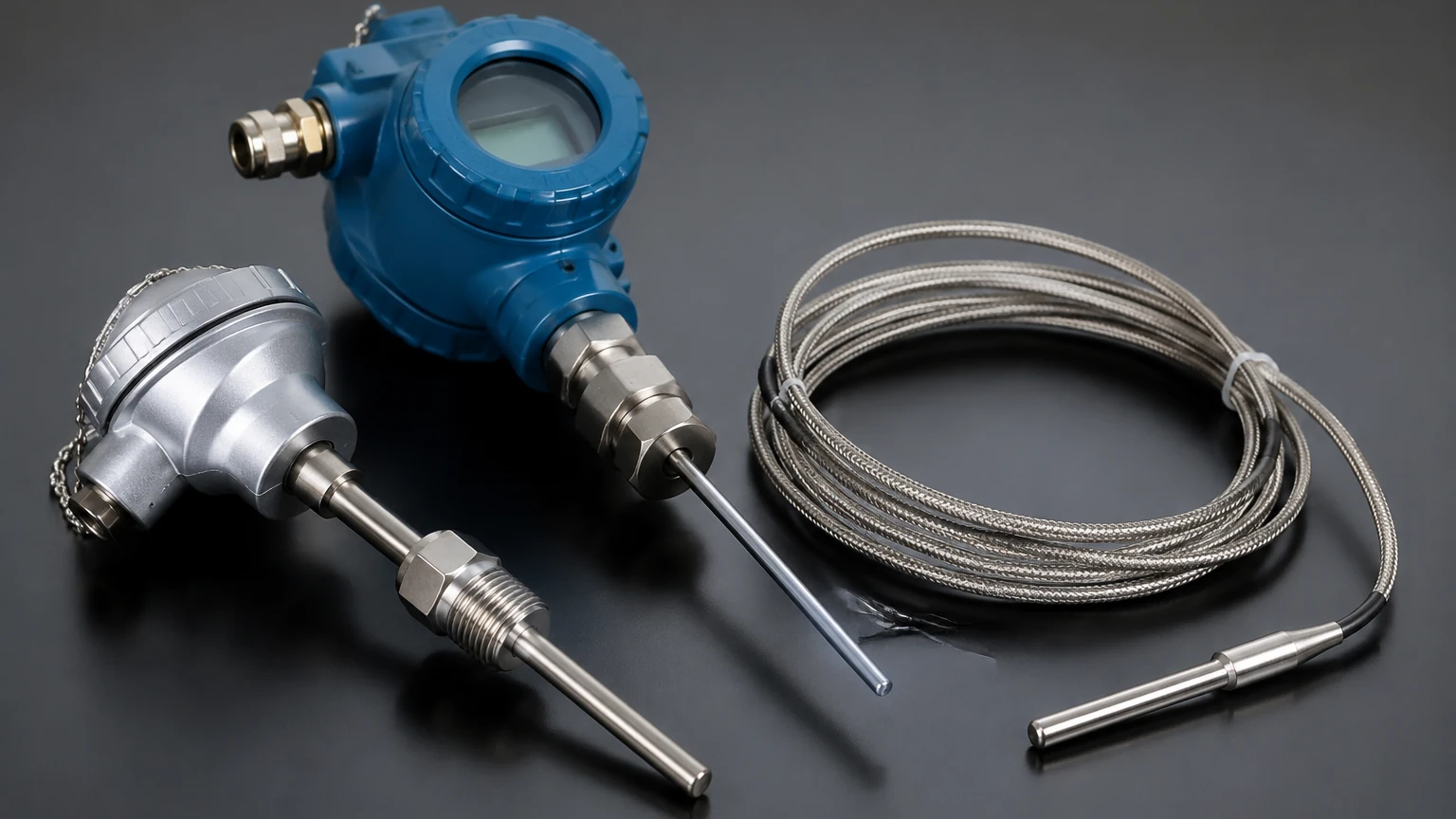
* Head-Mount: The transmitter is installed directly inside the connection head of the sensor assembly. This is space-efficient and protects the electronics within a rugged housing.
* DIN Rail-Mount: These units are installed in a centralized control cabinet. They are ideal for applications where the sensor environment is too hot or vibrates too intensely for integrated electronics.
* Field-Mount: Housed in separate, often explosion-proof or weather-proof enclosures, these are used in the most demanding outdoor or hazardous environments.
4. Galvanic Isolation
In environments with heavy machinery, electrical noise and ground loops are common. An isolated temperature sensor transmitter provides an electrical barrier between the input, output, and power supply, preventing noise from corrupting the measurement signal.
Practical Selection Table
The following table provides a comparison of common transmitter configurations used in industrial applications.
| Feature | Basic Analog Transmitter | Smart (HART) Transmitter | Universal Digital Transmitter |
| :— | :— | :— | :— |
| Input Type | Fixed (e.g., Pt100 only) | Selectable (RTD/TC) | Universal (RTD/TC/Ohm/mV) |
| Output | 4-20 mA Linear | 4-20 mA + Digital HART | 4-20 mA, HART, or Fieldbus |
| Configuration | Potentiometers (Manual) | Software / Handheld | Software / PC Interface |
| Isolation | Often Non-isolated | 1.5 kV to 2.5 kV AC | High Galvanic Isolation |
| Best Use Case | Simple, stable processes | Maintenance-heavy sites | Complex, high-EMI plants |
| Accuracy | ±0.1% to ±0.2% Span | ±0.05% to ±0.1% Span | High Precision (up to ±0.01%) |
Installation Considerations and Best Practices
Proper installation is as critical as the hardware itself. Even the most advanced temperature sensor transmitter will fail to provide accurate data if the physical installation is flawed.
Wiring and Shielding
To minimize the impact of EMI, use twisted-pair shielded cables for the 4-20 mA loop. The shield should be grounded at only one end (usually the control cabinet side) to prevent ground loops. For RTDs, ensure that all lead wires have the same gauge and length to maintain balanced resistance.
Environmental Protection
In water treatment or chemical plants, corrosive vapors can penetrate standard housings. Ensure the transmitter head has an appropriate IP rating (e.g., IP66 or IP67). If the process temperature is extremely high (above 500°C), use an extension neck between the process connection and the transmitter head to prevent the electronics from overheating. Most transmitters are rated for ambient temperatures up to 85°C (185°F).
Calibration and Configuration
Before deployment, the transmitter must be spanned. This involves setting the 4 mA point (e.g., 0°C) and the 20 mA point (e.g., 150°C). For smart transmitters, this can be done remotely. It is also a best practice to perform a "system calibration" or "loop check," where the sensor and transmitter are calibrated together in a dry block calibrator or oil bath to account for combined errors.
Limitations and Common Risks
While highly reliable, a temperature sensor transmitter is not without limitations. Awareness of these risks allows for better system design.
* Sensor Break Detection: If a sensor wire breaks, the transmitter must be configured to "fail high" (21.0 mA) or "fail low" (3.6 mA). If this is not set correctly, the control system might assume a valid temperature, leading to dangerous process conditions.
* Response Time: The transmitter adds a small amount of processing time to the measurement. In high-speed thermal cycling applications, this delay must be factored into the control loop tuning.
* Self-Heating: In RTD transmitters, the excitation current can cause the sensor element to heat up slightly. Quality transmitters use very low excitation currents (typically <0.3 mA) to minimize this effect.
For those looking to integrate these devices into broader monitoring systems, exploring the Main Page of specialized manufacturers like Welk can provide deeper insights into how temperature data complements level and pressure measurement in automated workflows.
Frequently Asked Questions (FAQs)
Q: Can I use a temperature sensor transmitter with any PLC?
A: Yes, provided the PLC has an analog input card capable of receiving a 4-20 mA signal. Most modern PLCs also support HART-enabled cards for advanced diagnostics.
Q: What is the maximum distance I can run a 4-20 mA signal?
A: The distance depends on the power supply voltage and the total loop resistance (wire resistance + transmitter load). Generally, distances of up to 1,000 meters (approx. 3,280 feet) are achievable without significant signal loss.
Q: Why choose a transmitter over wiring the sensor directly to the PLC?
A: Direct wiring (especially for thermocouples) requires expensive specialized extension wire. A transmitter allows you to use standard copper wire for the majority of the run, reduces noise interference, and provides a linearized signal that is easier for the PLC to process.
Q: How often should a temperature sensor transmitter be recalibrated?
A: For most industrial applications, an annual calibration check is sufficient. However, in highly regulated industries like pharmaceuticals or food production, semi-annual or quarterly checks may be required to meet compliance standards.
Conclusion
The temperature sensor transmitter is a silent workhorse in industrial automation. By converting delicate sensor signals into rugged, standardized outputs, it ensures that critical processes remain within their defined thermal boundaries. When selecting a transmitter, engineers must balance the need for accuracy and isolation with the practicalities of the installation environment. By adhering to rigorous selection and installation standards, facilities can ensure long-term reliability and minimize the risk of costly downtime. For comprehensive measurement solutions that integrate temperature, level, and flow, consulting with experienced manufacturers like Welk ensures that every component is optimized for the specific demands of the application.