Differential Pressure Flow Meter
Differential Pressure Flow Meter
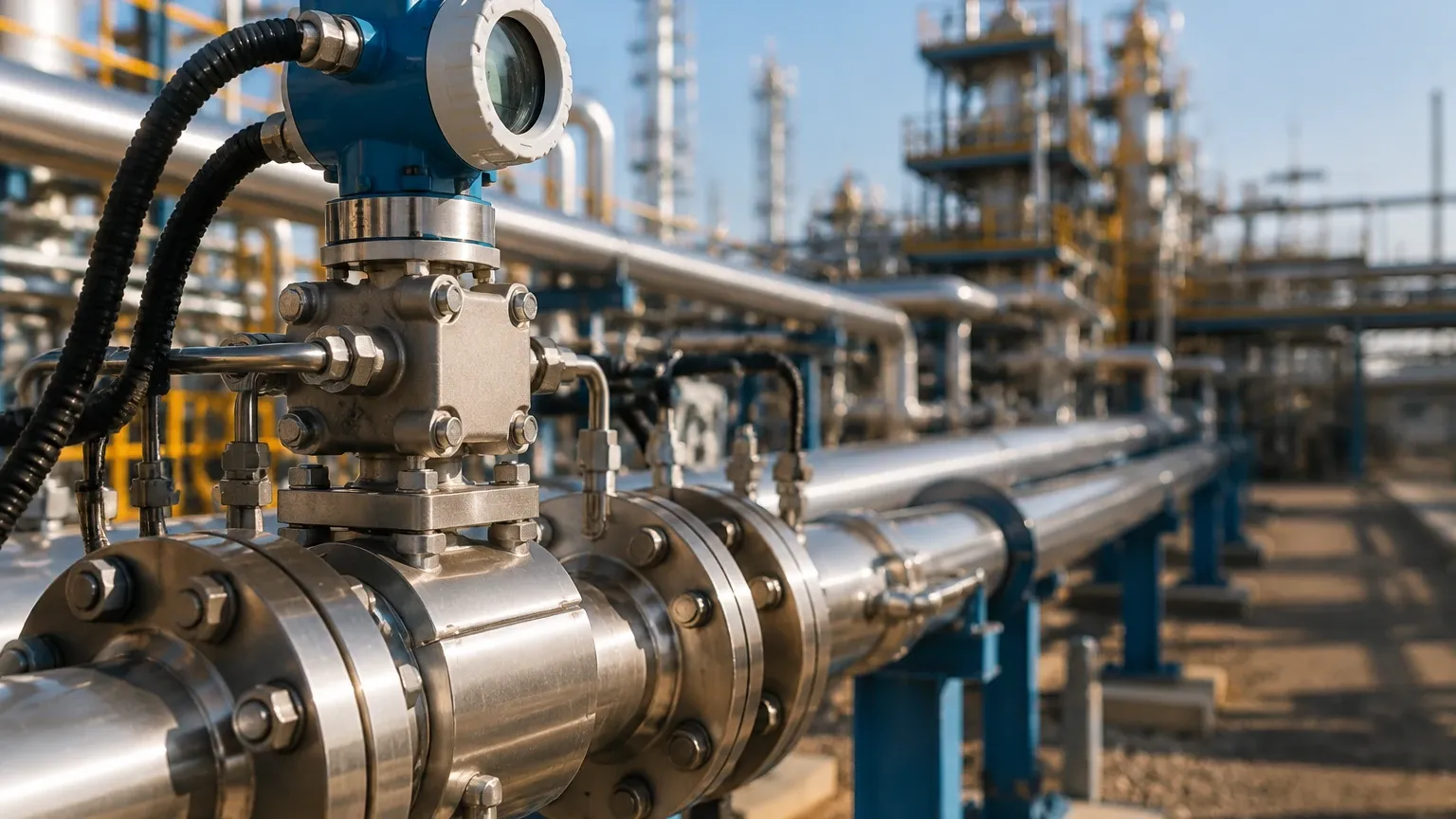
Differential pressure flow measurement remains one of the most widely adopted technologies in industrial process control. Despite the emergence of ultrasonic and Coriolis technologies, the differential pressure flow meter continues to be a cornerstone for measuring the flow of liquids, gases, and steam due to its robustness, versatility, and well-understood physical principles. In many industrial environments, the same differential pressure transmitters used for liquid level measurement in pressurized vessels are also deployed as the secondary element in flow measurement systems, making this technology a versatile asset for plant engineers.
Measurement Principles of Differential Pressure Flow Meters
The operation of a differential pressure flow meter is governed by Bernoulli’s principle, which states that as the speed of a moving fluid increases, the pressure within the fluid decreases. To measure flow, a physical constriction (the primary element) is placed within the pipe. This constriction causes a change in fluid velocity, which in turn creates a pressure drop across the element.
The Bernoulli Equation and Flow Calculation
According to the law of conservation of energy, the total energy of a fluid at any point in a closed system must remain constant. When fluid passes through a restriction, its kinetic energy increases as its velocity rises. To maintain the energy balance, the static pressure must decrease.
The relationship between the flow rate ($Q$) and the differential pressure ($ΔP$) is expressed by the following simplified equation:
$$Q = k \cdot \sqrt{\Delta P}$$
Where:
* Q is the volumetric flow rate.
* k is a flow coefficient that accounts for the geometry of the restriction, the pipe diameter, and fluid properties (such as density and viscosity).
* ΔP is the difference between the upstream pressure ($P1$) and the downstream pressure ($P2$).
A critical characteristic of the differential pressure flow meter is this square-root relationship. Because the flow is proportional to the square root of the pressure difference, the sensitivity of the meter decreases at lower flow rates, which typically limits the effective turndown ratio of these instruments to approximately 3:1 or 4:1 unless specialized transmitters are used.
Primary Elements: The Core of DP Flow Measurement
The "primary element" is the hardware that creates the pressure drop. Choosing the correct primary element is essential for accuracy and long-term reliability. For comprehensive technical support on selecting the right instrumentation for your specific process, you may visit the Main Page of our engineering resource.
1. Orifice Plates
The orifice plate is the most common primary element. It consists of a thin metal plate with a precisely machined hole (bore) in the center, installed between two flanges.
* Advantages: Low cost, easy to install, and standardized by international codes (ISO 5167).
* Disadvantages: High permanent pressure loss and susceptibility to wear or erosion over time.
2. Venturi Tubes
A Venturi tube features a tapered inlet and a diverging outlet. This design minimizes turbulence and allows for significant pressure recovery.
* Advantages: Extremely low permanent pressure loss, handles high flow rates, and is resistant to erosion.
* Disadvantages: Large physical footprint, heavy, and significantly higher initial cost than orifice plates.
3. Flow Nozzles
Flow nozzles are essentially a hybrid between an orifice plate and a Venturi tube. They feature a curved inlet that leads to a short cylindrical throat.
* Advantages: Excellent for high-velocity flows and high-temperature steam applications.
* Disadvantages: Higher pressure loss than a Venturi and more difficult to install than an orifice plate.
4. Pitot Tubes and Averaging Pitot Tubes
These elements measure the difference between the impact (total) pressure and the static pressure at a specific point or across a pipe cross-section.
* Advantages: Very low pressure drop and can be installed in large diameter pipes (up to several meters) with minimal cost.
* Disadvantages: Sensitive to velocity profile distortions and prone to clogging in dirty fluids.
Selection Criteria for Industrial Applications
Selecting a differential pressure flow meter requires a balance between accuracy requirements, fluid characteristics, and the allowable pressure drop in the system. The following table provides a comparison of common primary elements.
| Feature | Orifice Plate | Venturi Tube | Flow Nozzle | Pitot Tube |
| :— | :— | :— | :— | :— |
| Accuracy | ±1.0% to ±2.0% | ±0.5% to ±1.0% | ±1.0% | ±2.0% to ±3.0% |
| Permanent Pressure Loss | High (60-80% of ΔP) | Low (10-15% of ΔP) | Medium (40-60% of ΔP) | Very Low (<5% of ΔP) |
| Relative Cost | Low | High | Medium | Low |
| Suitability for Slurries | Poor | Good | Fair | Poor |
| Standardization | High (ISO 5167) | High | High | Moderate |
Installation Considerations
To ensure the accuracy of a differential pressure flow meter, the velocity profile of the fluid must be fully developed and symmetrical when it reaches the primary element. This is achieved through proper piping design.
1. Straight Pipe Runs: Most DP meters require a minimum length of straight pipe upstream and downstream of the element. A common rule of thumb is 10 to 20 pipe diameters ($D$) upstream and 5$D$ downstream. If elbows, valves, or pumps are located near the meter, these requirements may increase significantly.
2. Impulse Line Routing: The impulse lines (small diameter pipes connecting the primary element to the transmitter) must be installed correctly to prevent air or sediment from being trapped.
* For gas flow, the transmitter should ideally be mounted above the pipe so that any condensed liquid drains back into the process line.
* For liquid and steam flow, the transmitter should be mounted below the pipe so that air bubbles can rise back into the main line.
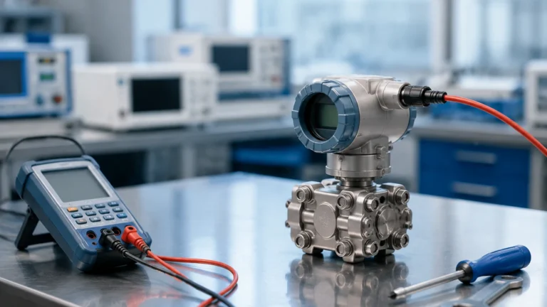
3. Manifolds: A 3-valve or 5-valve manifold is essential for maintenance. It allows the operator to isolate the transmitter from the process and equalize the pressure across the sensor for zero-point calibration without shutting down the entire flow line.
Limitations and Common Risks
While the differential pressure flow meter is highly reliable, it is not without limitations. Engineers must account for the following factors during the design phase:
* Turndown Ratio: As mentioned, the square-root relationship limits the effective range. If the flow rate drops below 25% of the calibrated maximum, the differential pressure becomes very small, leading to significant measurement errors.
* Permanent Pressure Loss: The energy used to create the differential pressure is not fully recovered (except in Venturi tubes). In large-scale operations, the pumping costs associated with this pressure loss can be substantial over the life of the instrument.
* Fluid Density Sensitivity: Since the calculation depends on fluid density, changes in temperature or pressure (especially in gas and steam applications) will cause errors. Multivariable transmitters that measure static pressure and temperature simultaneously are often used to provide "compensated" mass flow readings.
Frequently Asked Questions (FAQs)
Q: Can a differential pressure flow meter measure bidirectional flow?
A: Standard orifice plates are unidirectional. However, specialized bi-directional orifice plates or symmetric Venturi designs can be used with a bi-directional differential pressure transmitter to measure flow in both directions.
Q: How often should the primary element be inspected?
A: This depends on the fluid. For clean liquids, inspections may only be needed every few years. For abrasive slurries or corrosive chemicals, the orifice edge can round off, leading to an under-measurement of flow. Periodic visual inspection or "wet calibration" is recommended in these cases.
Q: What is the difference between a DP flow meter and a DP level meter?
A: The hardware (the transmitter) is often identical. However, the application differs. A flow meter measures the pressure drop across a restriction to calculate velocity, while a level meter measures the hydrostatic head (weight) of a liquid column to determine height. Both rely on the same fundamental principle of sensing small differences in pressure.
Q: Why is the square root extraction necessary?
A: The physical pressure signal generated by the primary element is proportional to the square of the flow velocity. To provide a linear 4-20mA signal that represents the actual flow rate, the transmitter or the control system (PLC/DCS) must perform a square root mathematical operation on the raw pressure data.
Conclusion
The differential pressure flow meter remains a vital tool in the industrial landscape, offering a balance of simplicity and performance. By understanding the specific requirements of the primary element and ensuring precise installation of the secondary transmitter, engineers can achieve highly accurate and repeatable measurements. For those looking to integrate these systems into broader process automation or level control frameworks, exploring the technical specifications on the Main Page can provide the necessary data for informed decision-making.