Fmr62b
Fmr62b
In the landscape of industrial automation, the precision of level measurement directly correlates with process safety, efficiency, and inventory management. The fmr62b represents a significant advancement in radar level measurement technology, specifically utilizing the 80 GHz frequency band. As industries transition from traditional mechanical or lower-frequency electronic sensors, understanding the engineering principles and application nuances of high-frequency radar like the fmr62b is essential for instrumentation engineers and plant managers.
This guide provides a technical overview of 80 GHz radar technology, the specific capabilities of the fmr62b, and practical considerations for its deployment in complex industrial environments. For a broader look at available measurement technologies, engineers can Review product options and application support to find the most suitable hardware for their specific process requirements.
The Physics of 80 GHz FMCW Radar Measurement
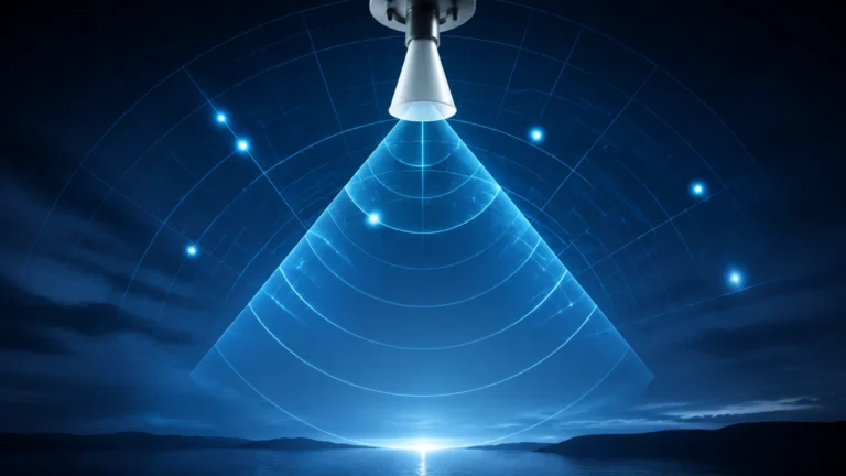
The fmr62b operates on the Frequency Modulated Continuous Wave (FMCW) principle. Unlike pulse radar, which measures the time-of-flight of a single microwave pulse, FMCW radar emits a continuous signal with a constantly changing frequency.
Frequency Modulation and Distance Calculation
During the measurement cycle, the transmitter sweeps through a defined frequency bandwidth. The signal is reflected by the surface of the medium and received by the antenna. Because the transmitter is continuously changing its frequency, there is a frequency difference between the signal currently being emitted and the reflected signal received. This difference, known as the beat frequency, is directly proportional to the distance between the sensor and the material surface.
The Advantage of 80 GHz
The move to the 80 GHz band from the traditional 26 GHz or 6 GHz bands offers several physical advantages:
1. Narrower Beam Angle: For a given antenna size, a higher frequency results in a more focused beam. An 80 GHz radar can achieve a beam angle as narrow as 3°, whereas a 26 GHz radar might require a much larger antenna to achieve even 8° or 10°.
2. Higher Resolution: The wider bandwidth available at 80 GHz allows for better separation of the signal from noise and reflections from internal tank structures.
3. Smaller Antenna Footprint: High-frequency components allow for more compact sensor designs, making them suitable for installation on small nozzles or in tight spaces.
Technical Specifications and Performance of the fmr62b
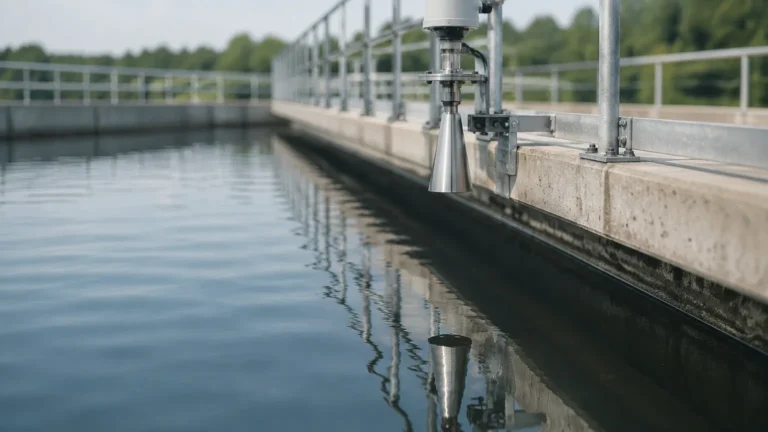
The fmr62b is engineered primarily for liquid applications, particularly those involving aggressive media or stringent hygienic requirements. It is a non-contact sensor, meaning the instrument itself does not touch the process medium, which reduces wear and maintenance needs.
Key Performance Indicators
* Measuring Range: Typically up to 80 meters (approximately 262 feet).
* Accuracy: High-precision versions offer an accuracy of ±1 mm (0.04 inches).
* Process Temperature: Capable of operating in environments ranging from -40 °C to +200 °C (-40 °F to +392 °F).
* Process Pressure: Designed to withstand pressures from vacuum up to 25 bar (362 psi).
* Frequency: 80 GHz W-band.
Antenna Design
The fmr62b often features a PTFE-filled, flush-mounted horn antenna or a drip-off antenna design. The "drip-off" geometry is critical in applications where condensation or buildup might occur; the shape encourages droplets to run off the antenna surface, preventing signal attenuation or "blindness" caused by moisture accumulation.
Selection Criteria: 80 GHz vs. 26 GHz
Choosing between different radar frequencies requires an analysis of the vessel geometry and the physical properties of the medium. The following table outlines the typical selection criteria used by engineers when evaluating the fmr62b against lower-frequency alternatives.
| Feature | 80 GHz (e.g., fmr62b) | 26 GHz Radar | 6 GHz Radar |
| :— | :— | :— | :— |
| Beam Angle | Very Narrow (approx. 3° – 6°) | Medium (approx. 8° – 15°) | Wide (approx. 20° – 30°) |
| Tank Obstacles | Easily avoids internal pipes/agitators | May require software mapping | Highly susceptible to interference |
| Nozzle Height | High tolerance for long nozzles | Limited by nozzle diameter | Requires large diameter nozzles |
| Accuracy | Highest (±1 mm) | High (±2 mm to ±5 mm) | Moderate (±5 mm to ±10 mm) |
| Dust/Vapor | Good penetration, but sensitive to heavy steam | Excellent penetration | Best penetration for extreme conditions |
| Small Tanks | Ideal due to narrow beam | Possible, but difficult | Not recommended |
Application Scenarios in Industrial Automation
The fmr62b is versatile, but it excels in specific scenarios where traditional level measurement fails or provides unreliable data.
1. Small Vessels and Narrow Tanks
In small process vessels, internal structures like heating coils, ladders, and agitators are often in close proximity to the radar's path. The narrow beam of the 80 GHz signal allows the fmr62b to "see" past these obstacles to the liquid surface without the need for complex false-echo suppression mapping.
2. Aggressive and Corrosive Media
Because the fmr62b can be equipped with a completely integrated PTFE antenna, it is highly resistant to chemical attack. This makes it a standard choice for acid storage tanks, caustic soda tanks, and other chemical processing units where contact-based sensors (like hydrostatic or float switches) would corrode rapidly.
3. High-Precision Inventory Management
For custody transfer or high-value chemical storage, the ±1 mm accuracy of the fmr62b ensures that inventory levels are tracked with extreme precision. This reduces the "uncertainty" factor in plant-wide mass balance calculations.
4. Hygienic Applications
In the food, beverage, and pharmaceutical industries, the flush-mounted antenna design complies with hygienic standards (such as 3-A or EHEDG). The lack of gaps or crevices prevents bacterial growth, and the non-contact nature ensures no contamination of the product.

Installation Guidelines for Optimal Signal Integrity
Correct installation is paramount to achieving the rated accuracy of an 80 GHz radar. While the fmr62b is more forgiving than lower-frequency models, certain engineering rules apply.
Nozzle Considerations
* Nozzle Diameter: The antenna should ideally be smaller than the nozzle diameter to avoid edge reflections.
* Nozzle Height: Unlike 26 GHz radars, the 80 GHz signal is less affected by the nozzle walls. However, the antenna should still ideally extend slightly past the nozzle or be flush with the tank ceiling to minimize interference.
Mounting Position
* Distance from Wall: The sensor should not be mounted in the center of the tank (to avoid multiple reflections) nor too close to the wall (to avoid signal interference). A common rule is to mount the sensor at 1/4 to 1/6 of the tank diameter from the wall.
* Orientation: The device should be mounted vertically, perpendicular to the liquid surface. If the tank has a sloped bottom or if the surface is turbulent, an alignment device may be required to optimize the return signal.
Blocking Distance (Dead Zone)
Every radar sensor has a "blocking distance" or "dead zone" immediately below the antenna where measurement is not possible. For the fmr62b, this is typically around 50 mm to 100 mm. Engineers must ensure that the maximum expected level of the liquid does not enter this zone, as it will result in an error or a loss of signal.
Potential Limitations and Risk Mitigation
While 80 GHz technology is robust, it is not a universal solution for every process. Engineers should confirm the following before final selection:
1. Extreme Steam and Condensation: While the drip-off antenna helps, extremely dense steam can attenuate 80 GHz signals more than 6 GHz signals. In high-pressure steam boiler applications, a lower frequency or a guided wave radar (GWR) might be more reliable.
2. Heavy Foam: Light, airy foam can sometimes be transparent to radar, while dense, thick foam can reflect the signal prematurely or absorb it. If heavy foam is present, testing or the use of a stilling well may be necessary.
3. Dielectric Constant (DC): Radar relies on the reflection of waves at the interface of materials with different dielectric constants. If a liquid has a very low DC (e.g., certain liquefied gases or oils), the reflection may be weak. The fmr62b is sensitive enough to handle most low-DC liquids, but the maximum measuring range may be reduced.
Frequently Asked Questions (FAQ)
Q: Can the fmr62b be used for solids?
A: While the fmr62b is optimized for liquids, 80 GHz technology is also used for solids (often under different model designations like FMR67B). For solids, the narrow beam is particularly useful for avoiding the "slopes" and "cones" formed by bulk materials.
Q: Does the fmr62b require periodic calibration?
A: In most standard applications, the fmr62b does not require recalibration after the initial commissioning. Because it has no moving parts and the measurement is based on the speed of light, the device remains stable over time. However, in regulated industries, annual verification may be required.
Q: How does the fmr62b handle agitators?
A: Thanks to the 3° beam angle, the fmr62b can often be positioned so that the signal path completely misses the agitator blades. If the beam does hit the agitator, the high frequency allows the software to easily distinguish between the moving blades and the relatively stable liquid surface.
Q: Is Bluetooth commissioning safe in industrial plants?
A: Yes, the fmr62b typically includes secure, encrypted Bluetooth communication. This allows technicians to configure the device from the ground using a smartphone or tablet, which is significantly safer than climbing to the top of a tall tank in hazardous areas.
For more technical data and to explore the full range of industrial level measurement solutions, including radar, ultrasonic, and hydrostatic transmitters, please visit the Main Page. Selecting the right instrument involves balancing frequency, antenna design, and process conditions to ensure long-term reliability and accuracy.