E Radar
E Radar
In the landscape of modern industrial automation, the term "e radar"—referring to electronic radar level measurement systems—represents the pinnacle of non-contact sensing technology. These instruments have largely superseded mechanical level indicators in critical applications across the chemical, oil and gas, and water treatment sectors. As a professional manufacturer, Welk provides a comprehensive suite of e radar solutions designed to meet the rigorous demands of high-pressure, high-temperature, and corrosive environments.
Understanding the nuances of e radar technology is essential for process engineers and procurement specialists. This guide explores the underlying physics, selection criteria, and installation protocols required to ensure long-term reliability and accuracy in level measurement.
Fundamental Principles of E Radar Measurement
Electronic radar level meters operate on the principle of electromagnetic wave reflection. Unlike ultrasonic sensors, which rely on sound waves and are susceptible to air temperature and pressure changes, e radar utilizes high-frequency microwaves that travel at the speed of light. This allows for precise measurement regardless of the gas composition or vacuum conditions within a vessel.
Time of Flight (ToF)
The most basic form of e radar measurement is the Time of Flight principle, often associated with pulsed radar. The sensor emits a short microwave pulse toward the surface of the medium. The pulse is reflected back to the antenna, and the electronics calculate the distance based on the time interval between transmission and reception. Since the speed of light is constant, the distance (D) is calculated as $D = (c \times t) / 2$, where $c$ is the speed of light and $t$ is the travel time.
Frequency Modulated Continuous Wave (FMCW)
Modern high-performance e radar systems, particularly those operating at 80 GHz, frequently utilize FMCW technology. Instead of sending discrete pulses, the transmitter emits a continuous signal with a constantly changing frequency (a frequency sweep). When the reflected signal is received, it is compared to the signal being emitted at that exact moment. The difference in frequency (the "beat frequency") is directly proportional to the distance. FMCW offers significantly higher resolution and a better signal-to-noise ratio compared to traditional pulsed systems, making it ideal for measuring low-dielectric liquids or materials in agitated tanks.
Frequency Categorization in E Radar Systems
The performance of an e radar device is heavily influenced by its operating frequency. Welk offers instruments across the three primary industrial bands:
1. 6 GHz (C-Band): These lower-frequency sensors are less affected by foam, heavy vapors, or surface turbulence. However, they require larger antennas to maintain a narrow beam angle, making them suitable for large outdoor sumps or tanks where nozzle size is not a constraint.
2. 26 GHz (K-Band): This is the "workhorse" frequency for many industrial applications. It offers a balance between a relatively narrow beam and the ability to penetrate moderate dust or steam. It is commonly used in chemical storage and water processing.
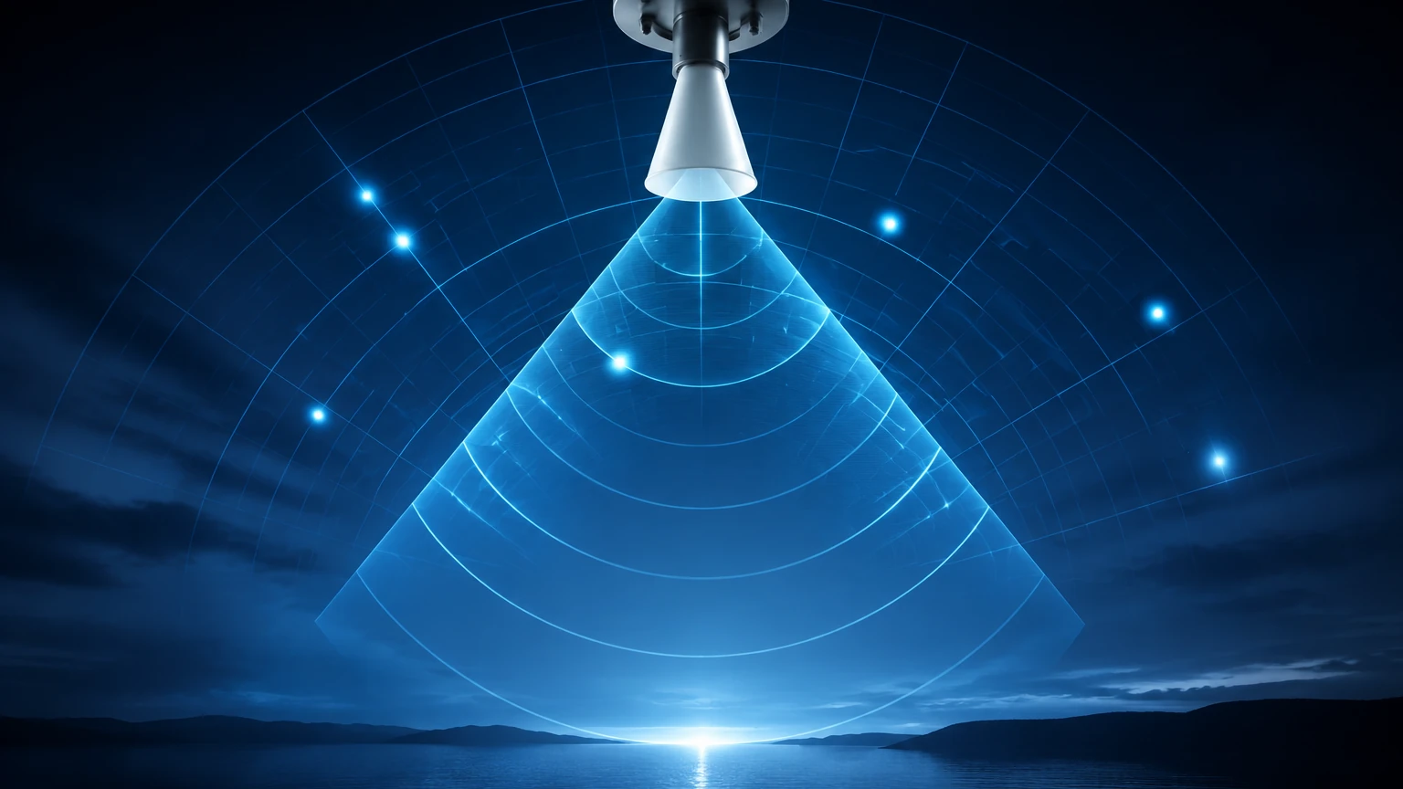
3. 80 GHz (W-Band): The current state-of-the-art in e radar. The high frequency allows for extremely small antennas and a very narrow beam angle (often as low as 3 degrees). This makes it possible to install the sensor in narrow nozzles or tanks with internal obstructions like agitators or heating coils without interference.
Comparison of E Radar Technologies
When selecting a level measurement solution, it is important to distinguish between non-contact radar and Guided Wave Radar (GWR). While both fall under the e radar umbrella, their applications differ significantly.
| Feature | Non-Contact E Radar | Guided Wave Radar (GWR) |
| :— | :— | :— |
| Measurement Method | Free-space microwave emission | Microwaves guided along a probe/cable |
| Surface Contact | No contact with media | Probe is submerged in media |
| Best For | Corrosive liquids, hygienic apps | Low dielectric fluids, interface measurement |
| Obstruction Sensitivity | High (requires clear path) | Low (signal follows the probe) |
| Maintenance | Extremely low | Periodic cleaning of probe may be required |
| Max Range | Up to 120 meters | Up to 30-60 meters (cable dependent) |
Selection Criteria for Industrial Applications
To ensure the selected e radar instrument performs optimally, several technical factors must be confirmed during the engineering phase.
Dielectric Constant (εr)
The dielectric constant of the medium is the most critical factor in determining signal strength. Materials with high dielectric constants, such as water (εr ≈ 80), reflect radar waves very effectively. Hydrocarbons and powders often have low dielectric constants (εr < 2), which result in weaker reflections. For very low dielectric materials, FMCW 80 GHz or Guided Wave Radar is typically recommended to ensure a reliable signal return.
Process Conditions
* Temperature: Standard e radar sensors can handle up to 150°C, but specialized high-temperature versions with ceramic seals can operate in environments exceeding 400°C.
* Pressure: Instruments are available for vacuum conditions and high-pressure reactors up to 16 MPa (160 bar).
* Chemical Compatibility: The wetted parts, such as the antenna or lens cover, must be compatible with the process media. Common materials include PTFE, PFA, and 316L Stainless Steel.
Vessel Geometry
The height and diameter of the tank, as well as the presence of internal structures, dictate the required beam angle. A narrow beam (80 GHz) is preferred for tall, narrow silos or tanks with internal baffles to avoid "false echoes" from the tank walls or equipment.
Installation Considerations and Best Practices
Correct installation is paramount for the accuracy of e radar systems. Even the most advanced 80 GHz sensor can fail if poorly positioned.
1. Nozzle Height and Diameter: The antenna should ideally extend slightly beyond the bottom of the mounting nozzle to prevent signal interference from the nozzle edge. If the nozzle is very long, a sensor with a narrow beam angle or a nozzle extension must be used.
2. Avoid the Center: In cylindrical tanks, do not install the sensor in the exact center. This prevents the "parabolic effect," where multiple reflections from the tank walls converge at the center, creating significant noise.
3. Distance from Wall: Maintain a minimum distance from the tank wall (typically 200mm or 1/10th of the tank height) to avoid interference.
4. Inlet Stream Avoidance: Never install the e radar directly above the filling inlet. The falling product will interfere with the microwave signal and may cause erratic readings.
5. Agitators and Obstructions: If an agitator is present, the sensor should be positioned so the beam path does not intersect the blades. If this is unavoidable, most modern Welk radar units feature "False Echo Suppression" software to map out and ignore these static or periodic reflections.
Limitations of E Radar
While highly versatile, e radar technology has specific limitations:
* Heavy Foam: Extremely thick, dense foam (like shaving cream) can absorb the radar signal entirely, leading to a loss of signal. In these cases, Guided Wave Radar or hydrostatic transmitters may be more appropriate.
* Low Dielectric Solids: In very light powders with εr < 1.5, the signal may pass through the material and reflect off the bottom of the silo instead of the surface.
* Extreme Dust: While 26 GHz and 80 GHz handle dust well, extremely high concentrations of metallic dust can attenuate the signal.
Maintenance and Troubleshooting
One of the primary advantages of non-contact e radar is the lack of moving parts, which results in minimal maintenance. However, in applications involving crystallizing liquids or heavy condensation, the antenna lens may require periodic inspection. Many Welk e radar units are designed with a convex PTFE lens that sheds condensation naturally, reducing the need for manual cleaning.
If a "Signal Lost" error occurs, common troubleshooting steps include:
* Checking for buildup on the antenna face.
* Verifying that the dielectric constant setting in the software matches the actual media.
* Re-performing a false echo mapping to account for any new internal tank changes.
Frequently Asked Questions (FAQ)
Q: Can e radar measure the interface between two liquids?
A: Standard non-contact radar is generally not suitable for interface measurement as the signal reflects off the top layer. Guided Wave Radar (GWR) is the preferred technology for measuring the interface between, for example, oil and water.
Q: Is 80 GHz always better than 26 GHz?
A: Not necessarily. While 80 GHz offers better focus and accuracy, 26 GHz is often more cost-effective for simple storage tanks and can be more robust in the presence of heavy steam or certain types of foam.
Q: How does vacuum affect e radar?
A: Unlike ultrasonic sensors, radar does not require a medium (like air) to travel. Therefore, e radar performs perfectly in a vacuum.
Conclusion
Selecting the right e radar system requires a thorough understanding of the process environment and the physical properties of the media. By considering frequency, dielectric constants, and vessel geometry, engineers can implement a level measurement solution that provides years of maintenance-free service. As a dedicated manufacturer, Welk offers the technical expertise and hardware variety needed to solve the most challenging level applications. For more detailed specifications and to explore our full range of industrial instruments, please visit our Main Page.
By prioritizing factual engineering data and following established installation guidelines, facilities can achieve the high precision and safety standards required in today's industrial landscape.