Thermal Mass Flow Transmitter
Thermal Mass Flow Transmitter
In the landscape of industrial process control, measuring the movement of gases with precision is essential for efficiency, safety, and cost management. While many technologies measure the volume of a fluid, the thermal mass flow transmitter stands out for its ability to measure the mass flow of gases directly. This distinction is critical because gases are highly compressible; their volume changes significantly with variations in temperature and pressure. By measuring mass, engineers obtain a consistent data point that reflects the actual amount of gas molecules passing through a system, regardless of environmental fluctuations.
For professionals managing complex systems—ranging from wastewater treatment aeration to chemical processing—understanding the nuances of thermal mass flow measurement is a prerequisite for successful instrumentation. This guide explores the underlying physics, selection criteria, and practical installation requirements for these devices, while highlighting how they complement broader industrial measurement strategies, such as those found on the Main Page of leading instrumentation providers like Welk.
Understanding the Principles of Thermal Mass Flow Measurement
The operation of a thermal mass flow transmitter is rooted in the laws of thermodynamics, specifically the principle that a moving fluid will dissipate heat from a heated surface at a rate proportional to its mass flow rate. Unlike differential pressure meters or turbine meters, thermal transmitters do not have moving parts and do not require separate temperature or pressure compensation to determine mass flow.
The Physics of Heat Transfer
Most industrial thermal mass flow transmitters utilize two Resistance Temperature Detectors (RTDs). These sensors are typically made of platinum and are protected by a robust metal sheath (such as 316 Stainless Steel or Hastelloy).
1. The Reference Sensor: This RTD measures the actual temperature of the process gas.
2. The Active (Heated) Sensor: This RTD is supplied with power to maintain a specific temperature higher than that of the reference sensor.
As gas flows past the heated sensor, molecules carry heat away from the surface—a process known as convective heat transfer. The transmitter's electronics measure the amount of energy required to maintain the temperature differential between the two sensors. According to King’s Law, the heat loss is directly related to the mass velocity of the gas. Because the density of the gas is a function of its mass, the instrument provides a direct mass flow reading (e.g., kg/h or Nm³/h).
Constant Temperature vs. Constant Power
There are two primary methods used by transmitters to manage this heat transfer:
* Constant Temperature Differential: This is the most common industrial method. The electronics maintain a constant temperature difference (ΔT) between the heated and reference sensors. As flow increases, more power is required to maintain the ΔT. This power consumption is converted into a linear flow signal.
* Constant Power: In this configuration, a fixed amount of power is supplied to the heated sensor. The temperature difference between the two sensors is measured. As flow increases, the temperature of the heated sensor drops. This method is often used in low-flow applications but can be slower to respond to rapid flow changes.
Key Components and Design of a Thermal Mass Flow Transmitter
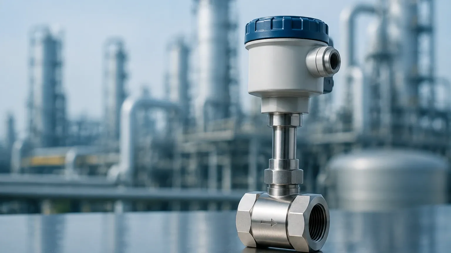
Industrial transmitters are designed to withstand harsh environments while maintaining high sensitivity. A standard unit consists of the probe (sensing element) and the transmitter (electronics).
The Probe Assembly
Probes are available in two main formats: insertion and in-line.
* Insertion Probes: These are designed for large pipes (typically >DN50 or 2 inches). They are inserted through a mounting flange or a compression fitting. They are cost-effective for large diameters and can often be installed via a "hot tap" method without shutting down the process.
* In-line Flow Bodies: For smaller pipes (DN15 to DN50), the sensors are built into a calibrated flow section. This ensures a known flow profile and higher accuracy, as the geometry of the measurement area is fixed.
The Transmitter Electronics
Modern transmitters, such as those offered by Welk, feature advanced digital signal processing (DSP). This allows for:
* Linearization: Converting the non-linear heat transfer signal into a linear 4-20mA or digital output (Modbus, HART).
* Temperature Compensation: While the measurement is inherently mass-based, the electronics adjust for changes in the gas's thermal properties at different temperatures.
* Data Logging: Storing flow totals and peak flow rates for regulatory reporting.
Technical Selection Criteria for Industrial Applications
Selecting the right thermal mass flow transmitter requires a detailed understanding of the process gas and the physical environment. Because the measurement relies on the thermal properties of the gas (specific heat and thermal conductivity), the transmitter must be calibrated for the specific gas mixture it will encounter.
Selection Matrix for Common Gases
| Application | Recommended Gas Calibration | Typical Pipe Size | Key Consideration |
| :— | :— | :— | :— |
| Compressed Air | Air (Dry) | DN25 – DN200 | Leak detection and energy cost monitoring. |
| Natural Gas | Methane (CH4) Mix | DN50 – DN600 | Explosion-proof (ATEX/IECEx) housing required. |
| Aeration Tanks | Air | DN100 – DN1000 | Low pressure drop is critical for blower efficiency. |
| Digester Gas | Biogas (CH4/CO2) | DN80 – DN300 | High moisture content; requires sensor heating. |
| Nitrogen Blanketing | Nitrogen (N2) | DN15 – DN100 | High sensitivity at very low flow rates. |
Evaluation Factors
1. Gas Composition: Is the gas a pure substance or a mixture? If the mixture ratio changes (e.g., in biogas), the accuracy of a thermal transmitter will degrade unless the device supports multi-gas programming.
2. Flow Range (Turndown Ratio): Thermal transmitters offer exceptional turndown ratios, often exceeding 100:1. This makes them ideal for applications where flow fluctuates from very low (leaks) to very high (peak production).
3. Pressure Drop: One of the greatest advantages of thermal technology is the negligible pressure drop, especially with insertion probes. This reduces the energy burden on compressors and blowers.
Installation Requirements and Best Practices
To achieve the specified accuracy (typically ±1% of reading), a thermal mass flow transmitter must be installed in a location with a fully developed flow profile. Turbulence is the primary enemy of accurate thermal measurement.
Straight Run Requirements
Like most flow technologies, thermal meters require a certain length of straight pipe before and after the sensor to eliminate swirls and eddies caused by elbows, valves, or reducers.
* Upstream: A minimum of 20 diameters (20D) of straight pipe is generally recommended.
* Downstream: A minimum of 5 diameters (5D) is required.
If these distances cannot be met due to space constraints, mechanical flow conditioners (vane or perforated plate types) must be installed to stabilize the flow.
Orientation and Depth
For insertion meters, the probe must be oriented correctly relative to the flow direction (usually indicated by an arrow on the sensor head). The sensing elements should be positioned at the center of the pipe, where the flow velocity is most representative of the average flow. In large pipes, the "center-point" is typically at 0.5 of the pipe diameter, but for pipes with high Reynolds numbers, an insertion depth of 1/8th or 1/4th of the diameter may be calculated based on the velocity profile.
Environmental Considerations
* Moisture: Thermal mass flow transmitters are sensitive to water droplets. If a droplet hits the heated sensor, it causes a sudden spike in the flow reading as the energy required to evaporate the water is misinterpreted as high gas flow. In saturated gas applications, the probe should be installed at an angle (e.g., 45 degrees) to allow moisture to run off, or a moisture separator should be installed upstream.
* Temperature Limits: Standard probes operate up to 150°C (302°F), but high-temperature versions can extend this to 450°C (842°F) for flue gas applications.
Limitations and Operational Risks
While highly versatile, thermal mass flow transmitters are not universal solutions. Engineers must be aware of the following limitations:
1. Gas Composition Sensitivity: As mentioned, the device is calibrated for a specific gas. If a meter calibrated for Nitrogen is used for Carbon Dioxide without reconfiguration, the error can exceed 20%.
2. Coating and Contamination: If the process gas contains oils, tars, or particulate matter that coats the sensor, the heat transfer rate will decrease. This leads to a "drift" in measurement. Regular inspection and cleaning are necessary in "dirty" gas applications.
3. Phase Changes: These meters are strictly for single-phase gas flow. They cannot measure liquids or steam (which is a vapor but behaves differently due to latent heat and condensation issues).
Integrating Flow and Level Measurement in Process Automation
In many industrial settings, flow measurement is only one piece of the puzzle. For instance, in a chemical storage tank, a Welk hydrostatic level transmitter might monitor the liquid volume, while a thermal mass flow transmitter monitors the nitrogen blanket gas used to prevent oxidation.
Integrating these data points allows for a comprehensive mass balance of the system. By combining reliable level measurement with accurate mass flow data, operators can identify losses, improve batch consistency, and ensure environmental compliance. When selecting instrumentation, it is beneficial to source from manufacturers who provide a holistic range of solutions, including radar level meters and ultrasonic sensors, to ensure compatibility across the control loop. You can explore a wide range of these integrated solutions on the Main Page of the Welk product catalog.
Frequently Asked Questions (FAQs)
Q: Do thermal mass flow transmitters require annual recalibration?
A: While the electronics are very stable, the sensors can be affected by the process environment. In regulated industries (like pharmaceutical or custody transfer), annual calibration is standard. In general industrial use, a "zero-check" performed under no-flow conditions is often sufficient to verify performance.
Q: Can I use a thermal mass flow transmitter for oxygen service?
A: Yes, but the meter must be specifically cleaned for oxygen service to remove all traces of hydrocarbons (oils/grease), which could ignite in a high-pressure oxygen environment. Ensure the manufacturer provides a certificate of oxygen cleaning.
Q: How does the response time compare to other flow meters?
A: Thermal transmitters typically have a response time between 1 and 2 seconds. While slightly slower than some differential pressure transmitters, this is more than adequate for most process control and monitoring applications.
Q: Is it possible to measure flow in rectangular ducts?
A: Yes. Insertion thermal mass flow transmitters are frequently used in large HVAC or exhaust ducts. In these cases, the cross-sectional area of the duct must be programmed into the transmitter to convert velocity into a volumetric or mass flow rate.
By adhering to these engineering principles and selection guidelines, B2B stakeholders can ensure that their investment in thermal mass flow technology provides the long-term accuracy and reliability required for modern industrial operations.