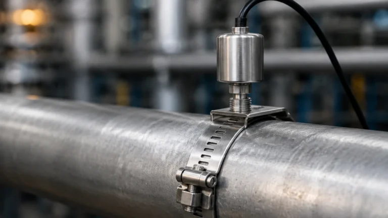
Ultrasonic Flow Meter for Gas
Ultrasonic Flow Meter for Gas
In the landscape of industrial instrumentation, the measurement of gas flow presents unique challenges compared to liquid flow. Gases are compressible, often vary in composition, and are highly sensitive to changes in temperature and pressure. The ultrasonic flow meter for gas has emerged as a preferred solution for high-accuracy applications, ranging from custody transfer of natural gas to process monitoring in chemical plants. This guide provides a technical overview of how these instruments operate, how to select them, and the critical installation factors that ensure long-term reliability.
Measurement Principles of Ultrasonic Gas Flow Meters
Before selecting an instrument, it is essential to understand the physics governing ultrasonic measurement in gaseous media. Unlike liquid applications where Doppler-shift technology is sometimes used for aerated fluids, gas flow measurement almost exclusively relies on the Transit-Time (Time-of-Flight) principle.
The Transit-Time Principle
Transit-time ultrasonic flow meters operate by transmitting and receiving acoustic pulses across a pipe at an angle. Two transducers act as both emitters and receivers. One transducer is located upstream and the other downstream.
When the gas is stationary, the time it takes for a pulse to travel from the upstream transducer to the downstream transducer ($t_{up-dn}$) is identical to the time taken for a pulse to travel in the opposite direction ($t_{dn-up}$). However, when gas is flowing, the pulse traveling with the flow (downstream) moves faster than the pulse traveling against the flow (upstream).
The velocity of the gas ($v$) is calculated using the difference in these transit times:
$$v = \frac{L}{2 \cos \theta} \left( \frac{1}{t_{up-dn}} – \frac{1}{t_{dn-up}} \right)$$
Where:
* L is the acoustic path length.
* θ is the angle of the path relative to the pipe axis.
Challenges in Gaseous Media
Measuring gas with ultrasound is significantly more difficult than measuring liquids due to acoustic impedance. Gases have much lower density than liquids, leading to poor coupling between the transducer and the fluid. This results in high signal attenuation. To overcome this, an ultrasonic flow meter for gas must utilize high-power transducers and sophisticated digital signal processing (DSP) to extract the signal from background noise. Furthermore, because the speed of sound in gas varies with temperature, pressure, and molecular weight, modern meters integrate sensors to compensate for these variables, often calculating the "speed of sound" (SOS) in real-time to verify gas composition or meter health.
Key Evaluation Criteria for Selection
Selecting the correct meter requires a thorough analysis of the process conditions. Engineers must look beyond the pipe size and consider the physical properties of the gas and the dynamics of the flow.
1. Gas Composition and Density
The molecular weight of the gas affects the speed of sound. For example, the speed of sound in hydrogen (approx. 1,300 m/s) is vastly different from that in carbon dioxide (approx. 270 m/s). If the gas composition is variable, such as in flare gas applications, the meter must be capable of handling a wide range of acoustic velocities. Additionally, a minimum operating pressure is often required (typically >1 bar or 100 kPa) to ensure sufficient gas density for signal transmission.
2. Flow Velocity and Turndown Ratio
One of the primary advantages of an ultrasonic flow meter for gas is its wide turndown ratio, often exceeding 100:1. However, at very high velocities (above 30–40 m/s), the signal may be "blown away" or distorted by turbulence. Conversely, at very low velocities (<0.1 m/s), the transit-time difference becomes so small that electronic jitter can impact accuracy.
3. Accuracy and Calibration
For custody transfer (fiscal measurement), accuracies of ±0.5% or better are required, necessitating multi-path configurations (3 to 18 paths) to account for flow profile distortions. For general process control or leak detection, a single-path or dual-path meter with ±1.0% to ±2.0% accuracy is usually sufficient.
4. Transducer Type: Wetted vs. Non-Invasive
* Wetted (In-line): Transducers are in direct contact with the gas. These offer the highest accuracy and are used for high-pressure natural gas pipelines.
* Clamp-on (Non-invasive): Transducers are mounted on the outside of the pipe. While convenient for retrofitting, they are highly dependent on pipe material and thickness and are generally less accurate for gas than for liquids.
Comparison of Gas Flow Technologies
The following table compares the ultrasonic flow meter for gas against other common industrial technologies used in similar applications.
| Feature | Ultrasonic (Transit-Time) | Orifice Plate (DP) | Turbine Meter | Thermal Mass |
| :— | :— | :— | :— | :— |
| Accuracy | High (0.5% – 1.0%) | Medium (1.0% – 3.0%) | High (1.0%) | Medium (1.0% – 2.0%) |
| Pressure Drop | Negligible | High | Moderate | Low |
| Moving Parts | None | None | Yes (Rotors) | None |
| Turndown Ratio | High (100:1) | Low (4:1) | Moderate (20:1) | High (50:1) |
| Maintenance | Low | High (Plate wear) | High (Bearing wear) | Low |
| Gas Type | Most clean gases | Most gases | Clean gases only | Specific calibrations |
Installation Considerations
To achieve the specified accuracy, the installation of an ultrasonic flow meter for gas must adhere to strict engineering standards. For more information on the full range of measurement technologies available for industrial processes, professionals can refer to the Main Page of instrumentation resources.
Straight Pipe Run Requirements
Ultrasonic meters are sensitive to flow profile disturbances caused by elbows, valves, and reducers. A standard installation typically requires:
* Upstream: 10 to 20 nominal diameters (D) of straight pipe.
* Downstream: 5 nominal diameters (D) of straight pipe.
If space is limited, a flow conditioner (vane or perforated plate) may be required to eliminate swirl and restore a fully developed flow profile.
Orientation and Positioning
For horizontal pipes, transducers should be mounted in the 3 o'clock and 9 o'clock positions. Mounting them at the top (12 o'clock) can lead to signal loss if gas moisture condenses, while mounting at the bottom (6 o'clock) can lead to debris or liquids shielding the transducer face.
Pressure and Temperature Taps
Since ultrasonic meters measure actual volume flow ($Q_a$), pressure and temperature measurements are required to calculate standard volume flow ($Q_s$) or mass flow. Temperature sensors should be installed downstream of the flow meter (typically 3D to 5D) to ensure they do not create turbulence that affects the ultrasonic paths.

Limitations and Common Risks
While highly versatile, the ultrasonic flow meter for gas is not a "one-size-fits-all" solution. Engineers must be aware of the following risks:
1. Ultrasonic Noise Interference: High-pressure drop across control valves can generate ultrasonic noise in the same frequency range as the flow meter (typically 100 kHz to 500 kHz). This noise can "deafen" the meter. Strategic placement or acoustic filters are necessary in these scenarios.
2. Liquid Entrainment: While some meters can handle small amounts of moisture, significant liquid droplets in the gas stream will scatter the ultrasonic signal, leading to "signal lost" errors.
3. Pipe Wall Attenuation: In clamp-on applications, if the pipe wall is too thick or has internal liners/scaling, the signal may not penetrate the gas effectively.
4. CO2 Content: High concentrations of Carbon Dioxide (CO2) significantly absorb ultrasonic energy. Special low-frequency transducers are often required for gases with >10% CO2 content.
Practical Selection Table by Application
| Application | Recommended Meter Type | Key Requirement |
| :— | :— | :— |
| Natural Gas Custody Transfer | Multi-path In-line | High precision & Redundancy |
| Flare Gas Monitoring | High-power Wetted | Wide velocity range & Low pressure |
| Compressed Air Audit | Clamp-on Ultrasonic | Portability & No pressure drop |
| Chemical Process Gas | Corrosion-resistant Wetted | Material compatibility (316SS/Hastelloy) |
| Nitrogen Blanketing | Single-path In-line | Low flow sensitivity |
Frequently Asked Questions (FAQs)
Q: Can an ultrasonic flow meter for gas measure bi-directional flow?
A: Yes. One of the inherent advantages of transit-time technology is its ability to measure flow in both directions with equal accuracy, provided the piping configuration supports it.
Q: Does the meter require periodic recalibration?
A: Because there are no moving parts to wear out, the "meter factor" remains very stable. However, in regulated industries, periodic electronic verification or laboratory flow calibration (every 2–5 years) is often mandated.
Q: How does gas pressure affect the measurement?
A: Higher pressure increases gas density, which actually improves the signal-to-noise ratio. The primary concern with pressure is ensuring the transducer seals and housing are rated for the maximum process pressure (e.g., PN16, PN40, or ANSI 600#).
Q: Is it possible to measure steam with these meters?
A: Yes, specialized high-temperature ultrasonic flow meters are available for steam. However, they must account for the extremely high velocities and the potential for condensate (two-phase flow), which can be challenging for standard gas meters.
Conclusion
The ultrasonic flow meter for gas represents a significant advancement in industrial measurement, offering a combination of high accuracy, wide turndown, and low maintenance. By understanding the transit-time principle and accounting for factors like gas density, ultrasonic noise, and piping geometry, engineers can implement reliable systems for even the most demanding gas applications. For those seeking comprehensive solutions in level and flow instrumentation, exploring the technical specifications on the Main Page is a recommended next step for project planning and device selection.