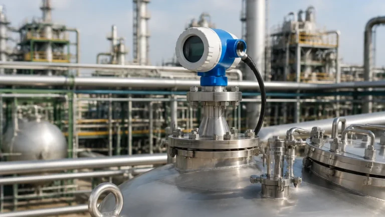
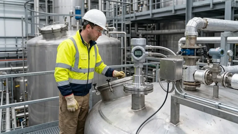
Fmr52 Radar Level Transmitter
Engineering Guide to the Fmr52 Radar Level Transmitter in Industrial Applications
In the landscape of modern process automation, precise level measurement is a cornerstone of operational safety and efficiency. Among the various technologies available, non-contact radar has emerged as the preferred solution for challenging environments. Specifically, the fmr52 radar level transmitter represents a specialized class of instrumentation designed to handle aggressive media and stringent hygienic requirements. This article provides a technical deep dive into the operating principles, selection criteria, and installation best practices for these instruments, helping engineers and procurement specialists make informed decisions for their facilities.
Understanding Radar Level Measurement Principles
Before selecting a specific instrument like the fmr52 radar level transmitter, it is essential to understand how Radar Level Meters function. Industrial radar sensors generally utilize one of two primary methods: Pulse Radar or Frequency Modulated Continuous Wave (FMCW).
Pulse Radar Technology
Pulse radar instruments emit short microwave pulses toward the material surface. The sensor measures the "Time of Flight" (ToF)—the duration it takes for the pulse to travel to the surface and reflect back to the receiver. Since the speed of light is constant, the distance is calculated using the formula: *Distance = (Speed of Light × ToF) / 2*.
FMCW Radar Technology
FMCW radar, often utilized in high-precision transmitters like the Fmr52, emits a continuous signal with a constantly changing frequency. The difference in frequency between the transmitted signal and the reflected signal is proportional to the distance. FMCW is generally superior in applications requiring high accuracy (up to ±1 mm) and better signal-to-noise ratios in turbulent tanks.
The Advantage of High Frequency
Modern radar transmitters often operate in the 80 GHz frequency range. Higher frequencies allow for smaller antenna sizes and narrower beam angles. A narrow beam is critical in industrial vessels because it minimizes interference from internal structures like agitators, ladders, or heating coils.
Technical Profile: The Fmr52 Radar Level Transmitter
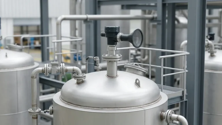
The fmr52 radar level transmitter is specifically engineered for applications where the medium is corrosive or where hygienic standards must be met (such as in the chemical or food and beverage industries). Its defining characteristic is the PTFE-clad horn antenna.
Key Design Features
1. PTFE Cladding: The entire antenna assembly is typically encased in Polytetrafluoroethylene (PTFE). This ensures that no metallic parts are exposed to the process media, providing excellent resistance to aggressive acids and bases.
2. Flush-Mounted Antenna: The design often features a flush-mounted lens, which prevents material buildup and condensation from clinging to the antenna surface, a common cause of signal loss in standard radar units.
3. Integrated Data Management: These units usually include HistoROM functionality, which stores device configuration and event logs, allowing for easy component replacement without recalibration.
Performance Specifications
* Measuring Range: Typically up to 30 meters (approximately 98 feet), though this depends on the dielectric constant of the medium.
* Process Temperature: Capable of operating in environments ranging from -40 °C to +200 °C (-40 °F to +392 °F).
* Process Pressure: Designed to withstand pressures from vacuum up to 16 bar (232 psi).
Selection Criteria for Industrial Radar Meters
Choosing the right radar instrument requires an analysis of the process environment. While the fmr52 radar level transmitter is versatile, engineers must evaluate the following factors to ensure long-term reliability.
Dielectric Constant (εr)
The dielectric constant of the liquid or solid being measured is the most critical factor in radar selection. Materials with high εr (like water, εr ≈ 80) reflect radar waves strongly. Materials with low εr (like hydrocarbons or solvents, εr < 2) reflect very little energy. If the εr is extremely low, a guided wave radar or a high-sensitivity FMCW transmitter may be required.
Process Conditions
* Turbulence: Surface ripples can scatter radar signals. In such cases, software algorithms for "echo smoothing" or the use of a stilling well are recommended.
* Foam: Heavy, dense foam can absorb radar signals entirely. If foam is a constant factor, ultrasonic or hydrostatic sensors might be considered, although high-frequency radar can sometimes penetrate light foam.
* Condensation: If heavy condensation is expected, the PTFE-clad lens of the Fmr52 is advantageous as it encourages droplets to shed rather than pool.
Selection Table: Radar Technology Comparison
| Feature | 26 GHz Pulse Radar | 80 GHz FMCW (Fmr52 Type) | Guided Wave Radar (GWR) |
| :— | :— | :— | :— |
| Accuracy | ±3 mm | ±1 mm | ±2 mm |
| Beam Angle | 8° – 20° | 3° – 8° | N/A (Follows Probe) |
| Corrosive Resistance | Moderate | Excellent (PTFE Clad) | Depends on Probe Material |
| Mounting | Top-down | Top-down | Internal Probe Required |
| Best Use Case | Large storage tanks | Small vessels with obstacles | Low dielectric liquids |
Installation Considerations and Constraints
Correct installation is as important as instrument selection. Even the most advanced fmr52 radar level transmitter will fail if positioned incorrectly.
1. Nozzle Geometry
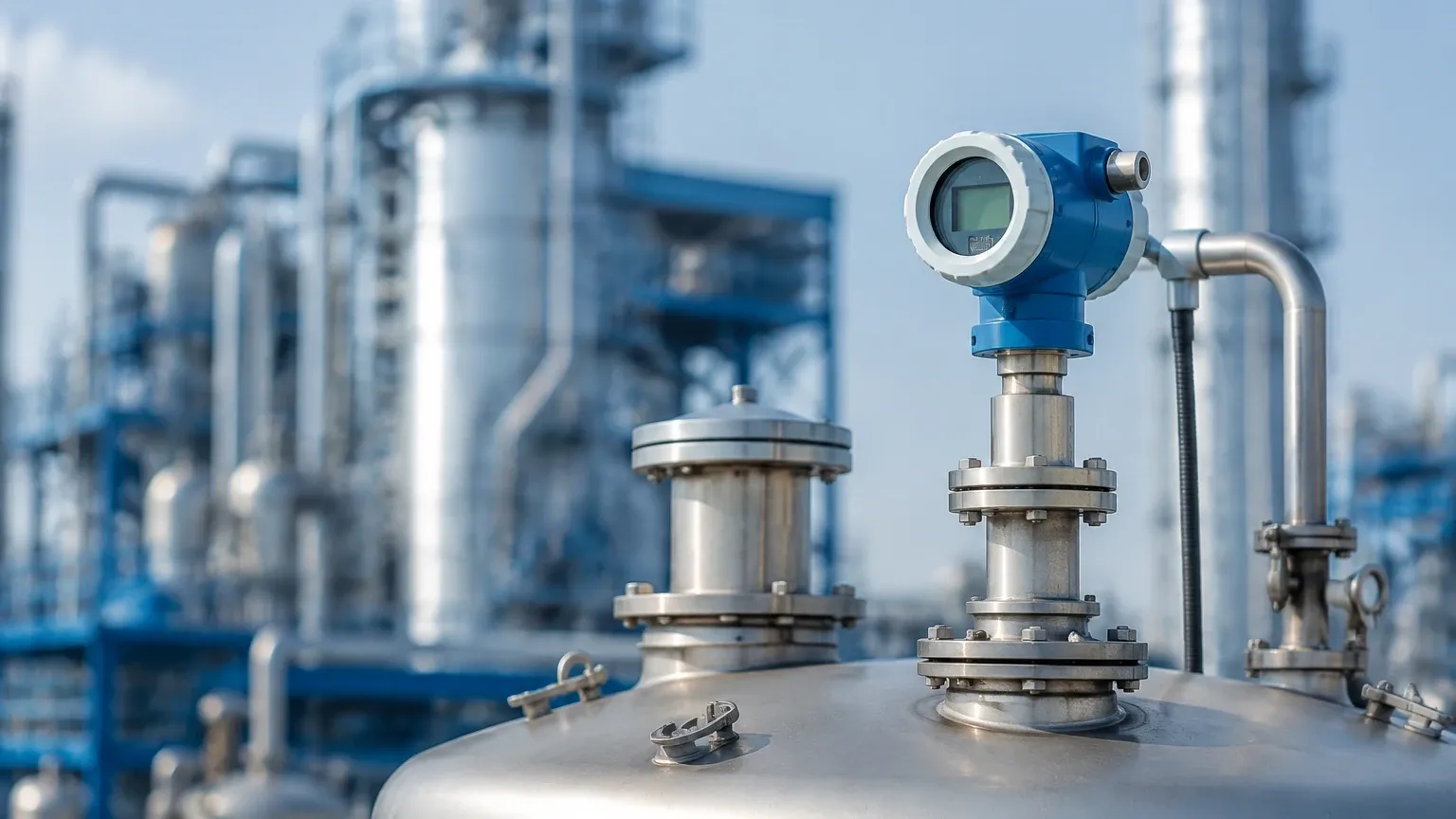
The antenna should ideally extend beyond the mounting nozzle. If the antenna is recessed within a long, narrow nozzle, the radar signal will reflect off the nozzle walls, creating a "ringing" effect that masks the true level. For the Fmr52, ensure the nozzle height ($H$) does not exceed the antenna length ($L$).
2. Positioning in the Vessel
* Avoid the Center: Do not install the transmitter in the center of a cylindrical tank. This can lead to multiple reflections (parabolic effect) that amplify noise.
* The 1/6 Rule: A common engineering rule of thumb is to install the sensor at 1/6th of the tank diameter from the wall. This provides a clear view of the surface while avoiding wall interference.
* Avoid the Fill Stream: Never install the sensor directly over the point where the tank is filled. The falling product will interfere with the radar signal.
3. Obstruction Management
If internal obstructions like agitator blades are unavoidable, use the transmitter’s "False Echo Suppression" or "Mapping" feature. During commissioning, the empty tank is scanned, and the software records the location of fixed reflections, allowing the sensor to ignore them during operation.
Limitations and Application Risks
While Radar Level Meters are highly robust, they are not universal solutions. Engineers should be aware of the following risks:
* The "Dead Zone" (Blocking Distance): Every radar has a minimum distance near the antenna where measurements are not possible. This is typically between 50 mm and 200 mm. If the tank is overfilled into this zone, the sensor may report an error or a frozen value.
* Vacuum Effects: While radar works in a vacuum (unlike ultrasonic sensors), the mechanical seals and flanges must be rated for vacuum service to prevent air ingress or sensor damage.
* Build-up on PTFE: Although PTFE is non-stick, extremely viscous materials (like hot bitumen or concentrated syrups) can still coat the lens. Regular inspection or the use of a purge air connection may be necessary.
Frequently Asked Questions (FAQ)
Q: Can the fmr52 radar level transmitter be used for solids?
A: While the Fmr52 is optimized for liquids and aggressive media, it can be used for some fine-grained solids. However, for bulk solids with high dust levels, a dedicated solids radar with a larger horn antenna is usually preferred to handle the signal scattering.
Q: How does temperature affect radar accuracy?
A: Radar signals are electromagnetic and are not significantly affected by air temperature or pressure changes, unlike ultrasonic waves. This makes radar much more stable in high-temperature reactors.
Q: Is it possible to shorten the antenna in the field?
A: No. The antenna of an fmr52 radar level transmitter is a factory-sealed unit, especially the PTFE-clad versions. Any modification will destroy the seal and the instrument's calibration.
Q: What maintenance is required?
A: Radar meters are generally maintenance-free because they have no moving parts. The primary maintenance task is checking the antenna lens for material build-up if the process involves splashing or heavy vapors.
Conclusion for International Buyers
When sourcing an fmr52 radar level transmitter or similar high-end Radar Level Meters, buyers should focus on technical compliance and manufacturer support. As a professional manufacturer, Welk emphasizes the importance of verifying process connections (DIN/ANSI flanges), signal outputs (4-20mA HART, Profibus, or Foundation Fieldbus), and local hazardous area certifications (ATEX, IECEx).
By following the measurement principles and installation guidelines outlined in this guide, industrial facilities can ensure high-precision level monitoring that withstands the rigors of aggressive chemical environments. Proper selection not only improves process safety but also reduces the total cost of ownership by minimizing downtime and maintenance requirements.