Radar Level Sensor Accuracy
Radar Level Sensor Accuracy: A Comprehensive Engineering Guide
In the landscape of industrial automation, the precision of level measurement directly impacts process safety, inventory management, and operational efficiency. Among the various technologies available, Radar Level Meters have emerged as the gold standard for non-contact measurement in challenging environments. However, achieving high radar level sensor accuracy is not merely a function of the device's datasheet; it is the result of matching the correct measurement principle with the specific physical constraints of the application.
This guide examines the technical foundations of radar accuracy, the variables that degrade signal integrity, and the engineering considerations required to optimize performance in B2B industrial environments.
1. Measurement Principles and Their Impact on Accuracy
Before selecting a sensor, it is essential to understand how different radar technologies derive distance. Radar level sensors primarily use two methods: Pulse Radar and Frequency Modulated Continuous Wave (FMCW).
Pulse Radar (Time of Flight)
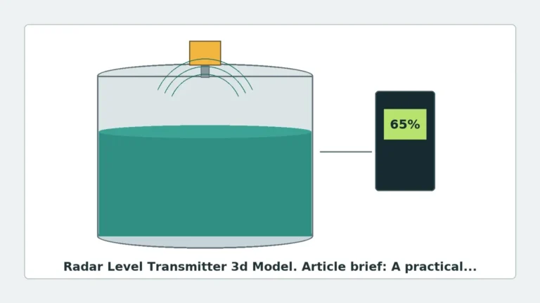
Pulse radar sensors emit short microwave pulses toward the medium's surface. The device measures the "Time of Flight" (ToF)—the time it takes for the pulse to travel to the surface and return to the antenna. Since the speed of light is constant, the distance is calculated as `Distance = (Speed of Light × Time) / 2`.
* Accuracy Characteristics: Pulse radar is generally cost-effective and suitable for large ranges. However, because the time intervals are incredibly small (nanoseconds), the resolution is often lower than FMCW, typically ranging from ±5 mm to ±20 mm.
Frequency Modulated Continuous Wave (FMCW)
FMCW radar does not send discrete pulses. Instead, it transmits a continuous signal with a frequency that changes linearly over time (a frequency sweep). The reflected signal is received and compared to the signal being transmitted at that exact moment. The difference in frequency (the "beat frequency") is directly proportional to the distance.
* Accuracy Characteristics: FMCW provides significantly higher resolution and signal-to-noise ratios. This technology allows for radar level sensor accuracy as precise as ±0.5 mm to ±2 mm, making it the preferred choice for custody transfer and high-precision chemical processing.
2. Defining Accuracy, Repeatability, and Resolution
In an industrial context, "accuracy" is often used as a catch-all term, but for engineering specifications, three distinct metrics must be evaluated:
1. Measured Error (Accuracy): The maximum positive or negative deviation between the value displayed by the sensor and the actual physical level. For high-end FMCW units, this is often expressed as ±1 mm.
2. Repeatability: The ability of the sensor to provide the same result under identical conditions. In many process control loops, repeatability is more critical than absolute accuracy, as it ensures consistency in batching.
3. Resolution: The smallest change in level that the sensor can detect. High-frequency radar (e.g., 80 GHz) offers superior resolution compared to low-frequency (6 GHz) models.
3. Technical Factors Influencing Radar Level Sensor Accuracy
Several physical and environmental variables can interfere with the microwave signal, leading to measurement errors.
Dielectric Constant (εr)
The dielectric constant of the medium is the most critical factor in signal reflection. Materials with high dielectric constants (e.g., water, εr ≈ 80) reflect microwaves strongly, providing a clear "echo" and high accuracy. Conversely, hydrocarbons and oils (εr ≈ 1.9 to 2.5) allow microwaves to penetrate the surface, resulting in a weaker return signal. If the εr is too low, the radar may "see through" the liquid to the tank bottom, causing significant errors.
Surface Turbulence and Foam
Agitators and boiling liquids create surface turbulence, which scatters the radar beam. While advanced signal processing can filter this noise, it inherently reduces the precision of the peak detection. Foam is more complex; dry, light foam may be transparent to radar, while thick, wet foam can absorb the signal entirely or create a false surface reflection.
Internal Tank Obstructions
Ladders, heating coils, and agitator blades create "false echoes." If these obstructions are located within the radar's beam angle, the sensor may lock onto a fixed metal structure rather than the liquid level. Modern Radar Level Meters utilize "False Echo Suppression" software to map these obstructions and ignore them, but their presence still complicates the accuracy profile.
4. The Role of Frequency: 6 GHz vs. 26 GHz vs. 80 GHz
The frequency of the radar signal determines the beam angle and the sensor's ability to handle difficult conditions.
| Frequency | Beam Angle | Best Use Case | Accuracy Impact |
| :— | :— | :— | :— |
| 6 GHz (C-Band) | Wide (approx. 20-30°) | Heavy steam, foam, or turbulence. | Lower accuracy due to wider beam picking up more tank interference. |
| 26 GHz (K-Band) | Medium (approx. 8-12°) | Standard industrial tanks, chemical storage. | Good balance of accuracy (±2-3 mm) and signal strength. |
| 80 GHz (W-Band) | Narrow (approx. 3-4°) | Small nozzles, tall narrow tanks, high-precision needs. | Highest radar level sensor accuracy (±1 mm) due to focused beam and high resolution. |
5. Selection Criteria for Industrial Applications
When choosing a level measurement solution, engineers must balance the required precision with the cost of the instrument. Welk, a professional manufacturer of industrial instrumentation, provides a variety of configurations to meet these specific needs.
Application Selection Table
| Industry | Application | Required Accuracy | Recommended Technology |
| :— | :— | :— | :— |
| Oil & Gas | Custody Transfer | ±0.5 mm to ±1 mm | 80 GHz FMCW Radar |
| Chemical | Corrosive Acid Storage | ±2 mm to ±3 mm | 26 GHz PTFE-lined Radar |
| Water Treatment | Open Channel/Basin | ±5 mm to ±10 mm | 26 GHz Pulse or Ultrasonic |
| Food & Beverage | Sanitary Batching | ±1 mm to ±2 mm | 80 GHz FMCW (Compact) |
| Mining/Solids | Cement Silo | ±10 mm to ±20 mm | 26 GHz High-Power Radar |
6. Installation Constraints for Optimal Precision
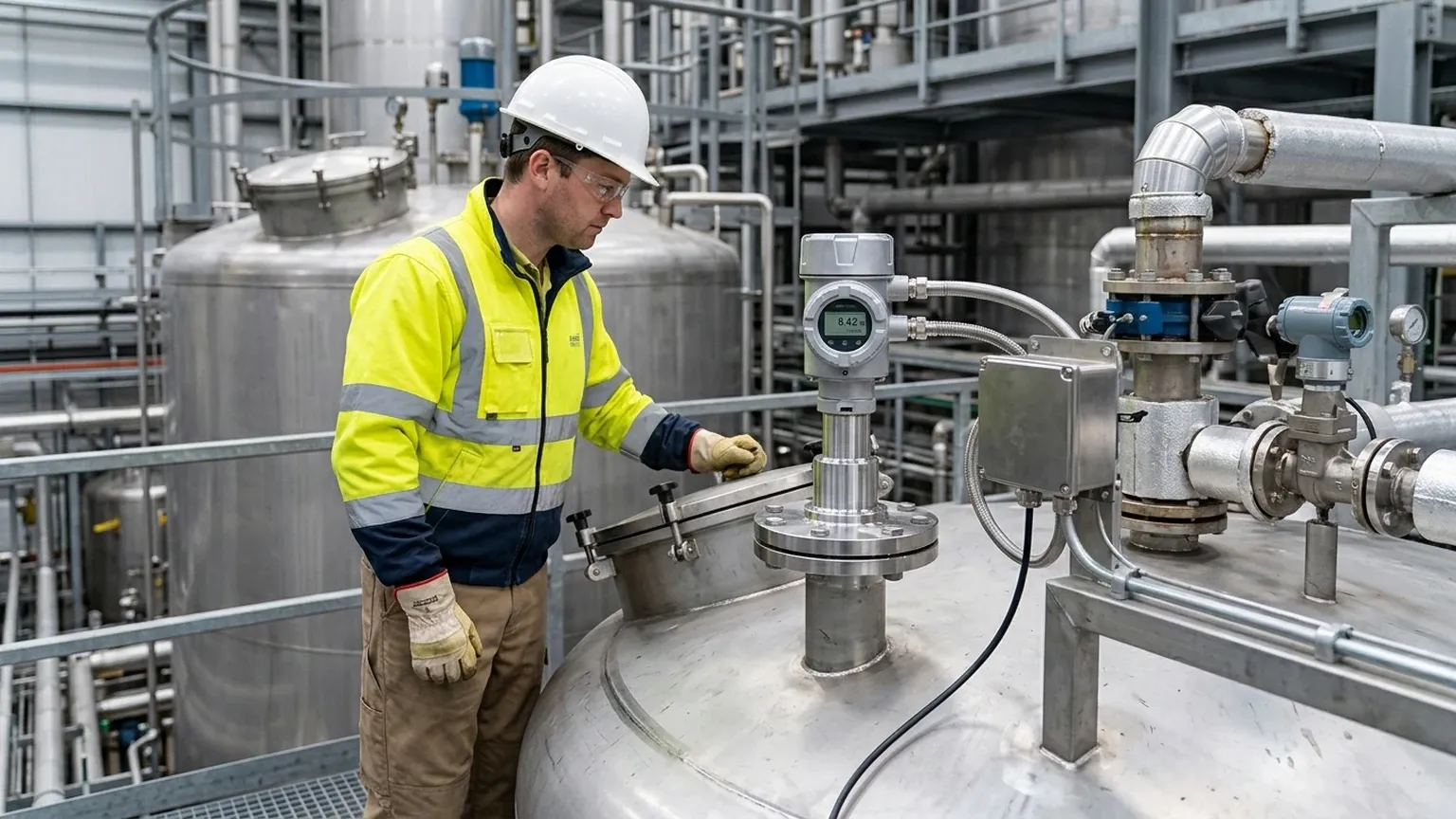
Even the most accurate sensor will perform poorly if installed incorrectly. To maintain radar level sensor accuracy, the following engineering guidelines should be followed:
1. Nozzle Height and Diameter: The antenna should ideally extend slightly beyond the mounting nozzle. If the nozzle is too long or narrow, the radar signal will bounce off the nozzle walls, creating a "ringing" effect that masks the true level at the top of the tank (the "Dead Zone").
2. Positioning: Sensors should be mounted at 1/6th to 1/4th of the tank diameter from the wall. Mounting too close to the wall causes interference from weld seams and sidewall buildup. Mounting in the center can lead to multiple reflections in domed-roof tanks.
3. Beam Path Clearance: Ensure the "keep-out zone" (the cone defined by the beam angle) is free of pipes, brackets, and inflow streams. If an inflow stream intersects the beam, the sensor will measure the falling liquid rather than the tank level.
4. Orientation: For solid materials, the sensor should be mounted with an aiming flange to tilt the antenna perpendicular to the angle of repose of the material.
7. Limitations and Environmental Interference
While radar is highly versatile, it is not infallible. Engineers should be aware of the following limitations:
* Vacuum and Pressure: While microwaves do not require a medium to travel (unlike ultrasonic waves), extreme pressure changes can affect the dielectric constant of the vapor space, though this effect is usually negligible (< 0.1% error).
* Heavy Dust: In solid applications, extreme dust can attenuate high-frequency signals. In these cases, a lower frequency (26 GHz) with a dust-purging system is often more reliable than an 80 GHz sensor.
* Condensation: Droplets on the antenna lens can refract the signal. Selecting a sensor with a convex (dripping) lens design or a PTFE shield helps mitigate this risk.
8. Maintenance and Calibration
To ensure long-term radar level sensor accuracy, a periodic maintenance schedule is recommended. Unlike mechanical gauges, radar meters have no moving parts, but they are subject to environmental fouling.
* Visual Inspection: Check the antenna for buildup or crystallization, especially in chemical applications. Even a thin layer of conductive material can significantly degrade signal quality.
* Verification: Periodically verify the sensor reading against a manual dip-tape measurement. This should be done at multiple points (e.g., 20%, 50%, and 80% of tank height) to check for linearity.
* Firmware Updates: Manufacturers like Welk often release signal processing improvements. Ensuring the device has the latest algorithms for false-echo suppression can improve performance in changing process conditions.
9. Frequently Asked Questions (FAQ)
Q: Does temperature affect radar level sensor accuracy?
A: Generally, no. Microwaves are electromagnetic waves and do not rely on air density. This makes radar superior to ultrasonic sensors in high-temperature applications. However, extreme heat may require a cooling extension to protect the sensor electronics.
Q: Can radar measure through a plastic tank?
A: Yes. If the tank is made of a non-conductive material like PE or PP, the radar signal can pass through the top of the tank, allowing for non-invasive measurement from the outside. Note that this will slightly reduce the signal strength.
Q: What is the "Dead Zone" or Blocking Distance?
A: This is the area directly below the antenna where the sensor cannot accurately measure. It is caused by the time required for the electronics to switch from transmit to receive mode. High-frequency FMCW radars have much smaller dead zones (often < 50 mm) than pulse radars.
Q: How do I handle measurement in a tank with a heavy agitator?
A: Use an FMCW radar with a narrow beam angle (80 GHz) to avoid the blades, and utilize the "Echo Mapping" feature to program the sensor to ignore the periodic reflections caused by the moving agitator.
Conclusion
Achieving optimal radar level sensor accuracy requires a holistic approach that considers the dielectric properties of the medium, the geometry of the vessel, and the specific frequency of the instrument. By understanding the trade-offs between Pulse and FMCW technologies and adhering to strict installation protocols, industrial operators can ensure reliable, high-precision level data for even the most demanding processes. For those seeking robust solutions, exploring the technical specifications of modern Radar Level Meters is the first step toward process optimization.