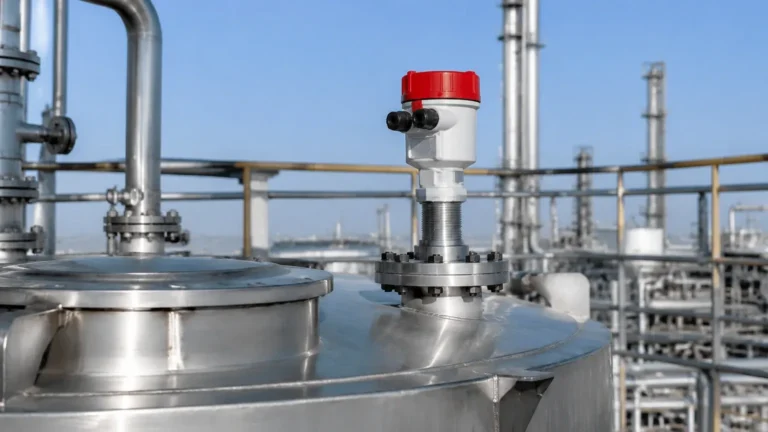
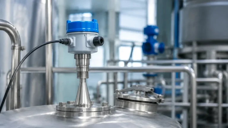
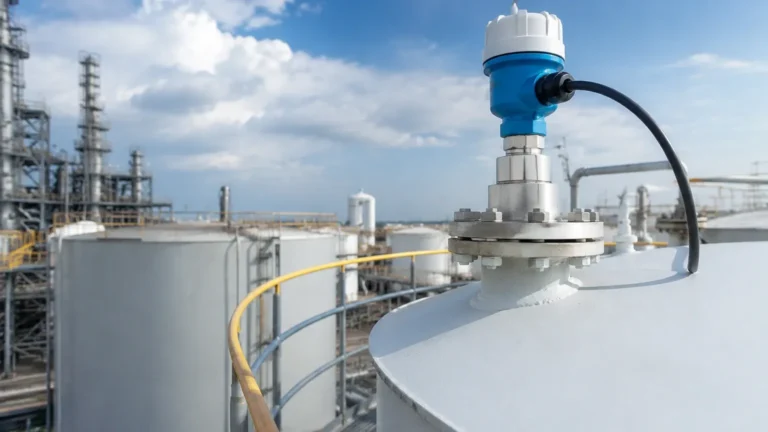
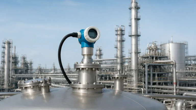
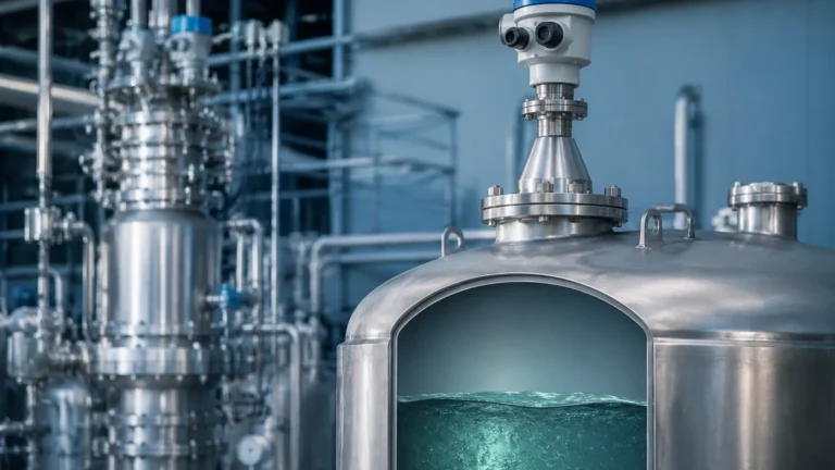
Radar Level Transmitter
Radar Level Transmitter: An Engineering Guide to Selection and Application
In the field of industrial process control, the accurate measurement of liquid and solid levels is critical for inventory management, process safety, and operational efficiency. Among the various technologies available, the radar level transmitter has emerged as a premier solution due to its non-contact nature and reliability in harsh environments. As a professional manufacturer, Welk provides a range of Radar Level Meters designed to meet the rigorous demands of water treatment, chemical processing, and oil and gas industries.
This guide explores the fundamental principles of radar technology, compares different technical approaches, and provides practical engineering considerations for selecting and installing these instruments.
1. Measurement Principles: How Radar Works
Radar (Radio Detection and Ranging) level measurement relies on the transmission of electromagnetic waves toward a target material. These waves travel at the speed of light. When they encounter a change in the dielectric constant (the surface of the medium), a portion of the energy is reflected back to the sensor. The instrument then calculates the distance based on the properties of the return signal.
There are two primary methods used by a modern radar level transmitter to process these signals:
Pulse Radar (Time of Flight)
Pulse radar instruments emit a series of short microwave pulses. The transmitter measures the time interval between the emission of the pulse and the reception of the echo. Since the speed of light is constant, the distance is calculated as:
*Distance = (Speed of Light × Travel Time) / 2*
Pulse radar is generally energy-efficient and suitable for simple liquid level applications where high precision is not the primary requirement.
FMCW (Frequency Modulated Continuous Wave)
FMCW radar transmits a continuous signal with a constantly changing frequency (a frequency sweep). When the reflected signal is received, it is compared to the signal being transmitted at that exact moment. The difference in frequency (the "beat frequency") is directly proportional to the distance to the material surface.
FMCW technology offers significantly higher accuracy and better signal-to-noise ratios compared to pulse radar, making it the preferred choice for complex industrial environments involving agitation, foam, or low-dielectric materials.
2. Frequency Bands and Their Impact
The performance of a radar level transmitter is heavily influenced by its operating frequency. Industrial radar instruments typically operate in three main bands:
* 6 GHz (C-band): These lower-frequency units have longer wavelengths, which allow them to penetrate heavy steam, dust, and some foam. However, they require larger antennas to maintain a focused beam, and their wider beam angle makes them susceptible to interference from internal tank structures.
* 26 GHz (K-band): This is the industrial standard for most liquid and solid applications. It offers a balance between antenna size and beam focus. It is highly effective for medium-range measurements in standard process vessels.
* 80 GHz (W-band): The latest advancement in radar technology. The high frequency allows for extremely narrow beam angles (as small as 3°) and very small antenna sizes. This makes 80 GHz transmitters ideal for tall, narrow silos or tanks with many internal obstructions, as the beam can easily avoid obstacles.
3. Contact vs. Non-Contact Radar
When specifying a system, engineers must choose between non-contact radar and Guided Wave Radar (GWR).
Non-Contact Radar
These instruments are mounted at the top of the vessel and emit waves through the air. Because they do not touch the medium, they are ideal for corrosive, hygienic, or extremely hot materials. Maintenance is minimal because there is no physical wear on the sensor.
Guided Wave Radar (GWR)
In GWR, the microwave pulse travels along a physical probe (rod or cable) that is immersed in the medium. This "guided" path concentrates the energy, making it much more efficient at detecting surfaces with low dielectric constants (such as oils or liquefied gases). GWR is also unaffected by turbulence, foam, or heavy dust in the headspace, as the signal is contained within the probe's immediate vicinity.
4. Engineering Selection Table
The following table provides a quick reference for selecting the appropriate technology based on common process conditions.
| Process Condition | Non-Contact Radar (26GHz/80GHz) | Guided Wave Radar (GWR) | Recommended Action |
| :— | :— | :— | :— |
| High Turbulence | Moderate Performance | Excellent | Use GWR with a bypass pipe or stilling well. |
| Heavy Foam | May lose signal | Good | Use GWR or low-frequency (6GHz) non-contact radar. |
| Low Dielectric (εr < 1.9) | Challenging | Preferred | Use GWR or 80GHz with high-sensitivity settings. |
| Internal Obstructions | 80GHz (Narrow beam) | Excellent | GWR avoids obstructions; 80GHz bypasses them. |
| Corrosive Liquids | Excellent (PTFE Flange) | Requires exotic alloys | Non-contact is generally more cost-effective. |
| Solids/Dust | Excellent (80GHz) | Risk of probe pull | Non-contact is preferred to avoid mechanical stress. |
5. Installation Best Practices
Even the most advanced radar level transmitter will fail if installed incorrectly. Engineers should adhere to the following guidelines:
* The Dead Zone (Blocking Distance): Every radar has a minimum detection range near the antenna (typically 50mm to 300mm). The highest liquid level must never enter this zone, or the measurement will become erratic.
* Mounting Position: Do not mount the transmitter in the center of a tank (unless the tank has a conical bottom) or too close to the wall. A common rule of thumb is to place the sensor at 1/6th of the tank diameter from the wall.
* Nozzle Geometry: The antenna should ideally extend slightly below the mounting nozzle to prevent signal ringing within the nozzle itself. If using a long nozzle, an 80GHz unit is preferred due to its narrow beam.
* Obstruction Clearance: Ensure the signal beam path is clear of ladders, agitator blades, and heating coils. If an obstruction is unavoidable, many modern Radar Level Meters offer "false echo suppression" software to map out and ignore these static reflections.

6. Limitations and Application Risks
While highly versatile, radar technology has specific limitations that must be addressed during the design phase:
1. Dielectric Constant (εr): This is the most critical factor. Materials with a very low dielectric constant (like liquid nitrogen or dry wood chips) reflect very little energy. If the εr is below 1.4, a stilling well or GWR is almost always required.
2. Heavy Foam: Dense, thick foam can absorb the radar signal entirely, preventing an echo from returning. In these cases, hydrostatic or ultrasonic sensors might be considered, though GWR often remains the best radar-based option.
3. Vacuum and Pressure: While the radar signal itself is unaffected by vacuum or high pressure, the mechanical seal of the transmitter must be rated for the process conditions. High-pressure applications often require specialized glass-to-metal seals.
7. Technical Checklist for International Buyers
When requesting a quote or specifying a radar level transmitter for a project, ensure the following technical data is confirmed:
* Medium Properties: Name of the medium, dielectric constant (if known), and whether it is liquid, solid, or slurry.
* Process Temperature & Pressure: Maximum and minimum operating ranges. Standard units typically handle up to 150°C; specialized versions can exceed 400°C.
* Vessel Dimensions: Total height, nozzle height, and diameter. This determines the required measuring range (e.g., 30m, 70m, or 120m).
* Connection Type: Flange size (DN or ANSI), thread type (G or NPT), or hygienic tri-clamp.
* Output Signal: 4-20mA HART is standard, but RS485 Modbus, Profibus, or Foundation Fieldbus may be required for integration into DCS/PLC systems.
* Certifications: Check for ATEX/IECEx (for hazardous areas), SIL2 (for safety loops), or food-grade (FDA) requirements.
8. Frequently Asked Questions (FAQ)
Q: Can a radar level transmitter measure through a plastic tank lid?
A: Yes. Because plastic is non-conductive and has a low dielectric constant, radar waves can pass through it. This allows for measurement without cutting a hole in the tank, provided the plastic is not too thick or reinforced with carbon fiber.
Q: How does dust affect 80GHz radar?
A: While 80GHz has a shorter wavelength, modern signal processing allows it to perform exceptionally well in dusty environments like cement silos or grain bins. The narrow beam prevents reflections from the sidewall buildup, which is a common failure point for older 26GHz units.
Q: Is calibration required on-site?
A: Most radar transmitters are pre-calibrated at the factory. However, "zero" and "span" alignment to the specific tank geometry is required during commissioning. This is usually done via a handheld communicator or laptop software.
Conclusion
The selection of a radar level transmitter requires a thorough understanding of the process environment and material characteristics. By choosing the correct frequency and mounting strategy, engineers can achieve maintenance-free, high-precision level measurement in almost any industrial application. For complex requirements, consulting with a manufacturer like Welk ensures that the instrument is tailored to the specific dielectric and mechanical constraints of the site.