Water Automatic
Water Automatic
In modern industrial processing and municipal management, the transition toward water automatic systems is no longer a luxury but a fundamental requirement for operational efficiency. Automated water level management involves the integration of precision sensing technology, control logic, and mechanical actuators to maintain fluid levels within specific parameters without manual intervention. This guide explores the technical foundations of automated level measurement, the principles governing various sensor technologies, and the practical considerations for implementing these systems in B2B environments such as water treatment plants, chemical processing facilities, and industrial automation loops.
Core Principles of Automated Level Measurement
Before selecting hardware for a water automatic system, it is essential to understand the physics behind the measurement. Level measurement is generally categorized into two types: point level detection and continuous level measurement.
Ultrasonic Time-of-Flight
Ultrasonic sensors operate by emitting high-frequency sound pulses (typically 20 kHz to 200 kHz) from a transducer. These waves travel through the air, reflect off the water surface, and return to the sensor. The system calculates the distance based on the time elapsed between emission and reception.
Because the speed of sound is influenced by air temperature, professional-grade ultrasonic sensors include integrated temperature compensation. In a water automatic context, these sensors provide a non-contact solution, which is ideal for corrosive or wastewater applications where physical contact would lead to sensor degradation.
Radar (Radio Detection and Ranging)
Radar level meters utilize electromagnetic waves rather than sound. High-frequency signals (often 26 GHz or 80 GHz) are transmitted toward the medium. The reflection is captured, and the distance is calculated using either Pulse Radar or Frequency Modulated Continuous Wave (FMCW) techniques.
Unlike ultrasonic waves, radar signals are largely unaffected by air temperature, pressure, or the presence of vapors and dust. This makes radar the gold standard for high-precision water automatic systems in challenging environments like pressurized tanks or outdoor reservoirs subject to wind and temperature fluctuations.
Hydrostatic Pressure
Hydrostatic measurement is a contact-based method that relies on the principle that the pressure at a specific point in a liquid is proportional to the height of the liquid column above it. The formula used is $P = \rho \cdot g \cdot h$, where $P$ is pressure, $\rho$ is the density of the fluid, $g$ is gravity, and $h$ is the height.
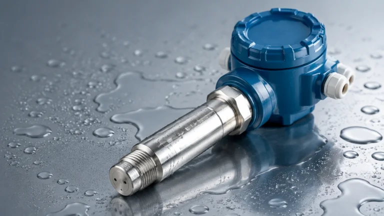
Submersible pressure transmitters are placed at the bottom of the tank or well. They measure the weight of the water and convert it into an electrical signal (typically 4-20mA). This method is highly reliable for deep wells and tanks where surface foam or turbulence might interfere with top-down non-contact sensors.
Magnetic and Float-Based Systems
Magnetic level gauges utilize a float containing a permanent magnet that rises and falls with the water level. This float moves inside a bypass chamber or along a guide rod. The magnetic field interacts with external switches or a continuous transmitter. In automated systems, magnetic switches are often used as redundant high-level or low-level alarms to prevent tank overflows or pump dry-running.
Designing the Water Automatic Control Loop
A functional water automatic system requires more than just a sensor; it requires a closed-loop control architecture. This loop typically consists of three stages:
1. Sensing: The level transmitter (radar, ultrasonic, or hydrostatic) provides a real-time data feed.
2. Logic/Control: A Programmable Logic Controller (PLC) or a dedicated level controller receives the signal. It compares the actual level against the "setpoint."
3. Actuation: Based on the logic, the controller sends a signal to a Variable Frequency Drive (VFD) for a pump or a motorized valve to adjust the flow of water.
For instance, in a municipal water tower, the water automatic system ensures that when the level drops below 3 meters, the supply pumps activate. Once the level reaches 8 meters, the pumps deactivate. This automation reduces energy consumption by preventing unnecessary pump cycling and ensures a constant head pressure for the distribution network.
Technical Selection Matrix
Selecting the right technology for a water automatic project depends on the specific environmental variables. The following table provides a comparison of common industrial sensors.
| Technology | Measurement Range | Accuracy | Contact Type | Key Advantage | Best Use Case |
| :— | :— | :— | :— | :— | :— |
| Ultrasonic | 0.3m – 20m | ±0.25% | Non-contact | Cost-effective | Open channels, sumps |
| Radar (80GHz) | 0.1m – 120m | ±1mm | Non-contact | Extreme precision | Process tanks, high vapor |
| Hydrostatic | 1m – 500m | ±0.5% | Contact | Simple installation | Deep wells, reservoirs |
| Magnetic Gauge | 0.3m – 6m | ±5mm | Contact | Visual + Electronic | Boilers, chemical tanks |
| Level Switch | Point only | N/A | Contact | High reliability | Overflow protection |
Installation Considerations for Automation
To ensure the longevity and accuracy of a water automatic setup, engineers must adhere to strict installation guidelines. Poor placement is the most common cause of system failure in industrial environments.
* Dead Zones (Blocking Distance): Every top-mounted sensor (ultrasonic and radar) has a "dead zone" directly beneath the transducer where it cannot measure. If the water level rises into this zone, the sensor may report an error or a false reading. The sensor must be mounted high enough to account for the maximum possible fill level.
* Internal Obstructions: In tanks with agitators, ladders, or internal bracing, sensors must be positioned to avoid these obstacles. Radar sensors with narrow beam angles (e.g., 3 degrees) are preferred in cluttered tanks to minimize false echoes.
* Stilling Wells: In applications with significant surface turbulence or foam, installing the sensor inside a stilling well (a vertical pipe) can provide a calm surface for more accurate measurement.
* Cable Protection: For hydrostatic sensors, the vent tube in the cable must remain unobstructed and protected from moisture. A blocked vent tube will lead to measurement errors as the sensor cannot compensate for changes in atmospheric pressure.

Limitations and Operational Challenges
While water automatic systems significantly improve efficiency, they are not without limitations.
1. Media Density Changes: Hydrostatic sensors are calibrated based on the density of the fluid. If the water contains varying concentrations of salts or chemicals that change its density, the level reading will drift unless recalibrated.
2. Surface Foam: Heavy foam can absorb ultrasonic signals, leading to a "loss of echo." In these scenarios, radar or hydrostatic sensors are more appropriate.
3. Vacuum and Pressure: Ultrasonic sensors require an air medium to transmit sound. They cannot function in a vacuum. Radar, being electromagnetic, functions perfectly in vacuums and high-pressure environments.
4. Signal Interference: In large-scale industrial plants, electromagnetic interference (EMI) from large motors can disrupt 4-20mA signals. Utilizing shielded cables and digital protocols like Modbus or HART can mitigate this risk.
Frequently Asked Questions (FAQ)
Q: Can I use an ultrasonic sensor for boiling water?
A: It is not recommended. Boiling water creates heavy steam and turbulence. Steam changes the density of the air, affecting the speed of sound and causing significant errors. Radar is the preferred choice for such applications.
Q: How often do hydrostatic sensors need recalibration?
A: In clean water applications, annual calibration is usually sufficient. However, in wastewater or silty environments, the sensor diaphragm may become fouled, requiring more frequent cleaning and verification.
Q: What is the benefit of an 80GHz radar over a 26GHz radar?
A: The 80GHz radar has a much narrower beam angle and a shorter wavelength. This allows it to ignore internal tank obstructions more effectively and provides better accuracy (down to ±1mm), which is critical for high-value chemical dosing in water automatic systems.
Q: Is it possible to automate a system without a PLC?
A: Yes. Many modern level transmitters come with integrated relay outputs. These can be wired directly to a pump starter or a valve actuator for simple "on/off" control without the need for a complex PLC.
Conclusion
Implementing a robust water automatic system requires a thorough evaluation of the physical environment, the required precision, and the integration capabilities of the hardware. By understanding the principles of ultrasonic, radar, and hydrostatic measurement, engineers can design systems that reduce waste, prevent environmental hazards, and optimize industrial throughput. For those looking to source high-quality instrumentation or seeking technical support for specific applications, reviewing comprehensive product options is the next logical step.
To explore detailed specifications and find the right instrument for your facility, visit the Main Page for professional-grade level measurement solutions.