Cip Flow Sensor
Cip Flow Sensor
In industrial processing, particularly within the food, beverage, pharmaceutical, and chemical sectors, hygiene is paramount. Clean-in-Place (CIP) systems are designed to clean the interior surfaces of pipes, vessels, process equipment, and fittings without disassembly. A critical component in the automation and validation of these cycles is the cip flow sensor. This device ensures that cleaning agents, rinses, and disinfectants move through the system at the correct velocity and volume to achieve the required mechanical scrubbing action and chemical contact time.
Effective CIP relies on the "Sinner’s Circle"—a combination of four variables: time, temperature, chemical concentration, and mechanical action (flow). Without an accurate flow sensor, operators cannot verify if the mechanical action was sufficient to remove stubborn residues, leading to potential batch contamination or inefficient use of water and expensive cleaning chemicals.
Measurement Principles for CIP Flow Sensors
Selecting the right technology for flow measurement in a CIP environment depends on the fluid properties and the specific requirements of the process. Several measurement principles are commonly employed.
Electromagnetic Flow Measurement
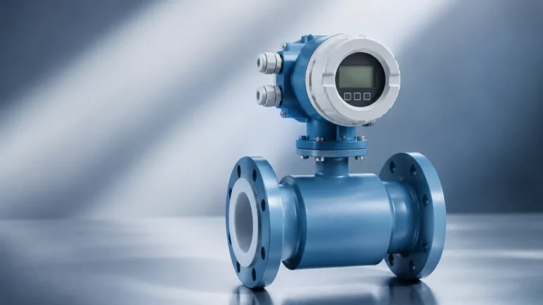
Electromagnetic flow meters (magmeters) are the industry standard for CIP applications involving conductive liquids. They operate based on Faraday’s Law of Electromagnetic Induction. When a conductive fluid (such as water or caustic cleaning solutions) flows through a magnetic field generated by the sensor, it induces a voltage proportional to the velocity of the fluid.
* Advantages: No moving parts to clog or wear, no pressure drop, and highly accurate for conductive fluids.
* Limitations: They cannot measure non-conductive fluids like deionized water or oils.
Ultrasonic Flow Measurement
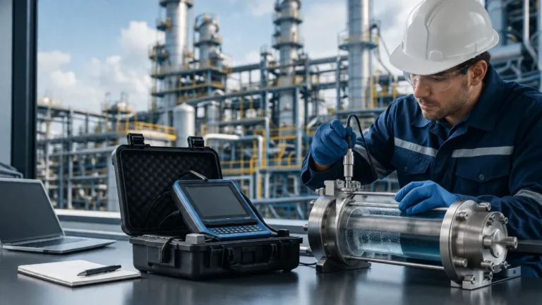
Ultrasonic sensors typically use the transit-time principle. Two transducers transmit and receive ultrasonic signals through the fluid. The difference in time taken for the signal to travel upstream versus downstream is proportional to the flow velocity.
* Advantages: Available in clamp-on designs that do not contact the fluid, maintaining maximum hygiene. They can measure non-conductive fluids.
* Limitations: Performance can be degraded by the presence of significant air bubbles or high concentrations of suspended solids, which are common during the initial rinse phase of a CIP cycle.
Thermal Mass Flow Measurement
Thermal sensors measure the heat dissipation from a heated sensing element to the flowing fluid. The rate of heat loss is directly related to the mass flow rate.
* Advantages: Excellent for detecting low flow rates and confirming that a pipe is full.
* Limitations: Generally slower response times compared to electromagnetic meters and can be sensitive to rapid temperature fluctuations during transitions between cold rinse and hot caustic cycles.
Technical Selection Criteria
When evaluating a cip flow sensor, engineers must look beyond basic flow range. The harsh environment of a CIP cycle—which includes rapid temperature shifts and aggressive chemicals—demands specific technical specifications.
| Feature | Requirement | Reason |
| :— | :— | :— |
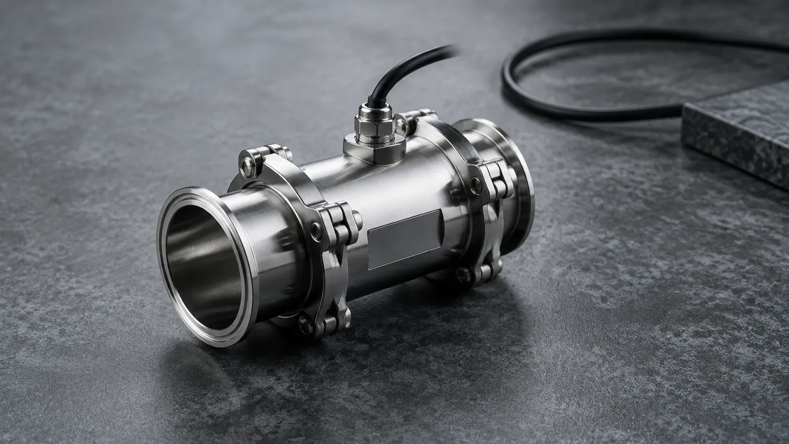
| Material | 316L Stainless Steel | Resistance to phosphoric acid, caustic soda, and chlorine. |
| Surface Finish | Ra < 0.8 μm | Prevents bacterial growth and ensures easy cleaning. |
| Temperature Rating | Up to 140°C (284°F) | Must withstand Steam-in-Place (SIP) sterilization. |
| Process Connection | Tri-clamp, DIN 11851, or SMS | Hygienic, leak-proof connections that eliminate dead spaces. |
| Ingress Protection | IP67 or IP69K | Protection against high-pressure washdowns and humidity. |
| Certifications | 3-A, EHEDG, or FDA | Ensures the design meets global food and drug safety standards. |
Installation and Engineering Considerations
Proper installation is as important as sensor selection for ensuring long-term accuracy and hygiene. Failure to follow installation guidelines can lead to "dead legs" where bacteria can proliferate or air pockets that cause erratic readings.
1. Orientation: For liquid applications, vertical installation with upward flow is preferred. This ensures the pipe is always full and helps naturally evacuate air bubbles. If horizontal installation is necessary, the sensor should not be placed at the highest point of the system (where air collects) or the lowest point (where sediment collects).
2. Straight Pipe Runs: Most flow sensors require a certain length of straight pipe upstream (typically 5 to 10 diameters) and downstream (3 to 5 diameters) to stabilize the flow profile. Without this, turbulence from elbows or valves will cause measurement errors.
3. Grounding: For electromagnetic sensors, proper grounding is essential to eliminate electrical noise that can interfere with the low-voltage signal generated by the flow.
4. Thermal Shock: CIP cycles involve rapid transitions from ambient temperatures to 85°C (caustic wash) and back. Ensure the sensor electronics are thermally decoupled from the process connection to prevent internal component fatigue.
Common Risks and Limitations
While modern sensors are robust, certain process conditions present ongoing risks to measurement integrity:
* Entrained Air: During the start of a CIP cycle, pipes are often partially filled with air. This can cause ultrasonic and electromagnetic meters to report "empty pipe" errors or provide wildly inaccurate spikes in flow data. Using an "empty pipe detection" feature is critical for PLC logic integration.
* Conductivity Shifts: If using an electromagnetic meter, the conductivity of the fluid must remain above a minimum threshold (typically 5 μS/cm). While cleaning chemicals are highly conductive, the final rinse with high-purity water may approach the limits of the sensor.
* Scaling and Coating: Over time, minerals from hard water or proteins from food products can coat the electrodes of an electromagnetic sensor. This acts as an insulator and reduces accuracy. Regular verification and periodic chemical cleaning of the sensor itself are required.
Integrating Flow and Level Data
In a complete industrial automation setup, flow sensors do not operate in isolation. They are part of a broader ecosystem that includes temperature probes, conductivity sensors, and level transmitters. While the flow sensor monitors the movement of fluids through the lines, level measurement instruments monitor the inventory of cleaning chemicals in the bulk tanks and the recovery of fluids in the return tanks.
For instance, a radar level meter or hydrostatic transmitter in the CIP supply tank ensures there is enough caustic solution to complete the programmed cycle. If the level is too low, the system should prevent the CIP pump from starting, regardless of what the flow sensor indicates. For engineers looking to optimize their entire tank and piping infrastructure, it is helpful to Review product options and application support on our Main Page to understand how level measurement technologies complement flow monitoring in hygienic environments.
Frequently Asked Questions (FAQ)
Q: What is the ideal flow velocity for a CIP cycle?
A: To achieve effective mechanical scrubbing, a minimum velocity of 1.5 to 2.1 meters per second (m/s) is generally recommended in the largest diameter pipe of the circuit. The flow sensor is used to verify that the pumps are maintaining this threshold.
Q: Can a CIP flow sensor be used for water and chemicals simultaneously?
A: Yes, provided the sensor materials (typically 316L SS and PEEK or PTFE liners) are compatible with both. Electromagnetic meters are excellent for this as they can handle varying concentrations of acids and bases without recalibration, provided the fluid remains conductive.
Q: How often should a CIP flow sensor be calibrated?
A: In regulated industries like pharmaceuticals, annual calibration is standard. In food and beverage, many facilities move to a 2-year cycle or use "internal verification" features built into modern digital sensors to extend calibration intervals.
Q: Why is 3-A certification important?
A: 3-A Sanitary Standards Inc. provides third-party verification that the equipment design prevents the entrapment of organic matter and allows for total sterilization. Using non-certified sensors in a food-grade line can lead to regulatory non-compliance and increased risk of spoilage.
Conclusion
The implementation of a dedicated cip flow sensor is a fundamental step toward process validation and resource efficiency. By accurately measuring the flow of cleaning media, manufacturers can reduce the duration of cleaning cycles, minimize water consumption, and ensure that every piece of equipment is sanitized to the highest standards. When combined with reliable level measurement in supply tanks, flow sensors provide the data necessary for a fully optimized and transparent Clean-in-Place operation.