Tr10
Tr10
In the landscape of industrial process control, accurate measurement is rarely the result of a single isolated variable. For professionals managing storage tanks, chemical reactors, or water treatment facilities, level measurement is often the primary objective. However, the accuracy of level data is frequently dependent on secondary variables, most notably temperature. The TR10, a modular resistance thermometer (RTD) assembly, serves as a cornerstone technology for providing the precise temperature data required to calibrate and correct level readings in real-time.
As a professional manufacturer of industrial level measurement instruments, Welk provides a wide range of solutions, including radar level meters and ultrasonic sensors, which often operate in tandem with temperature assemblies like the TR10. Understanding the integration of these technologies is essential for engineering reliable automation systems. For a comprehensive overview of primary measurement hardware, engineers should consult the Main Page of our technical catalog.
Understanding the Measurement Principles of TR10 Sensors
The TR10 is fundamentally a resistance thermometer, typically utilizing a Pt100 or Pt1000 platinum sensing element. Its operation is based on the physical property of electrical resistance in metals, which increases in a predictable, repeatable manner as temperature rises. This relationship is defined by the temperature coefficient of resistance (alpha), which for standard industrial platinum sensors is 0.00385 Ω/Ω/°C.
The RTD Element
The heart of the TR10 is the measuring insert. Platinum is the preferred material due to its chemical stability and wide temperature range (typically -200 °C to +600 °C). Unlike thermocouples, which generate a voltage based on the Seebeck effect, RTDs like the TR10 measure absolute resistance. This results in higher accuracy and better long-term stability, which is critical for process industries where a drift of even 0.5 °C can impact the calculated volume of a high-value fluid.
Wiring Configurations
To ensure the highest accuracy, TR10 assemblies are available in several wiring configurations:
- 2-Wire: The simplest form, but prone to errors caused by lead wire resistance. It is rarely used in precision industrial level applications.
- 3-Wire: The industrial standard. It uses a third wire to compensate for the lead resistance, assuming all wires have the same resistance. This is suitable for most level measurement density compensations.
- 4-Wire: The most accurate configuration. It completely eliminates the influence of lead wire resistance, making it ideal for laboratory-grade measurements or custody transfer applications.
The Critical Link Between Temperature and Level Measurement
While the TR10 measures temperature, its role in level measurement is one of "compensation." Many level measurement technologies are physically influenced by the temperature of the medium or the vapor space above it.
Hydrostatic Level Measurement and Density
Hydrostatic level transmitters measure the pressure exerted by a liquid column. The formula used is $P = ρ · g · h$, where $P$ is pressure, $ρ$ (rho) is density, $g$ is gravity, and $h$ is the height of the liquid.
Liquid density is not a constant; it changes as temperature fluctuates. For example, as a hydrocarbon in a storage tank warms up, it expands and its density decreases. Without a TR10 sensor to provide real-time temperature data to the control system, the hydrostatic transmitter would report a lower pressure and, consequently, an incorrect (lower) level, even if the physical volume has increased. By integrating TR10 data, the PLC or DCS can apply density correction factors to maintain accuracy.
Ultrasonic Level Measurement and the Speed of Sound
Ultrasonic sensors calculate distance by measuring the time it takes for a sound pulse to travel to the liquid surface and back. The speed of sound in air (or gas) is highly dependent on temperature ($c ≈ 331.3 + 0.606T$). A change of just 1 °C can result in a 0.18% error in distance. In deep tanks (e.g., 10 meters), this error becomes significant. High-quality ultrasonic systems often incorporate a TR10 or similar probe to monitor the air temperature in the tank headspace to adjust the sound-speed calculation.
Technical Specifications and Configurations
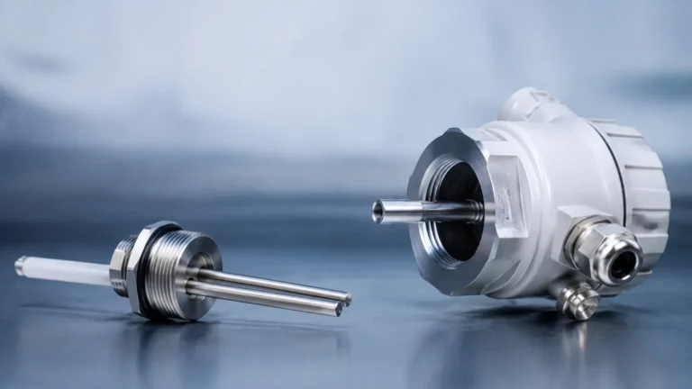
The TR10 is designed as a modular system, allowing it to be tailored to specific industrial environments. The assembly typically consists of the following components:
1. Connection Head: Usually made of aluminum, stainless steel, or plastic (for corrosive environments). It houses the terminal block or the temperature transmitter. Common forms include Form B or Form BUZ.
2. Temperature Transmitter: This optional component converts the resistance signal (Ohm) into a standardized 4-20 mA signal or a digital bus signal (HART, PROFIBUS, or FOUNDATION Fieldbus). This is essential for long-distance signal transmission to minimize interference.
3. Neck Tube: This provides a thermal buffer between the process connection and the connection head, protecting the electronics from extreme process temperatures.
4. Thermowell: The protective sheath that is permanently installed in the process. The TR10 measuring insert is placed inside the thermowell, allowing for sensor replacement without opening the tank or pipe.
Material Selection
Standard TR10 assemblies use 316L stainless steel for wetted parts. For aggressive chemical applications, materials like Hastelloy, Monel, or PTFE coatings are employed to prevent corrosion. In the context of Welk’s level measurement solutions, matching the metallurgy of the temperature sensor to the level meter is standard practice to ensure galvanic compatibility within the vessel.
Selection Criteria for Industrial Applications
Choosing the correct TR10 configuration requires an analysis of the process conditions. The following table provides a general selection guide for engineers:
| Application Parameter | Requirement | Recommended TR10 Feature |
| :— | :— | :— |
| Temperature Range | -50 to +250 °C | Standard Pt100 Thin-film element |
| Temperature Range | > 500 °C | Wire-wound Pt100 element |
| High Pressure | > 40 bar (4 MPa) | Solid-machined thermowell (Barstock) |
| Corrosive Media | Acids / Bases | Tantalum or PTFE-coated thermowell |
| Vibration | Agitated Tanks | Vibration-resistant (Vibe-Check) inserts |
| Hazardous Areas | Flammable Gas/Dust | ATEX/IECEx Explosion-proof (Ex d) or Intrinsic Safety (Ex i) |
When integrating these sensors with Welk's magnetic level gauges or radar systems, it is vital to ensure that the TR10 is positioned at a representative height in the tank to capture the average temperature of the medium.

Installation Guidelines and Best Practices
Correct installation of the TR10 is as important as the sensor's accuracy. Poor placement can lead to "thermal shunting" or measurement lag.
Immersion Depth
To minimize heat conduction errors, the sensor must be immersed deeply enough into the process. A general rule of thumb is an immersion depth of at least 10 times the diameter of the thermowell. For a standard 12mm diameter thermowell, the immersion should be at least 120mm. In small-diameter pipes, the sensor should be installed at an angle or in an elbow to achieve sufficient immersion.
Placement Relative to Level Meters
In tanks where Welk's radar or ultrasonic level meters are used, the TR10 should be placed away from the direct path of the signal beam to avoid interference. However, it should remain close enough to the level sensor to ensure the temperature data accurately reflects the conditions at the measurement point. In stratified liquids, multiple TR10 sensors at different heights may be required to calculate an average density.
Sealing and Process Connections
Process connections typically involve threaded (NPT/G), flanged, or hygienic (Tri-clamp) fittings. It is critical to ensure that the pressure rating of the connection exceeds the maximum possible process pressure. For high-pressure steam applications, welded thermowells are often preferred over threaded ones to prevent leaks.
Limitations and Maintenance of TR10 Assemblies
While highly reliable, TR10 sensors have specific limitations that must be acknowledged:
- Response Time: Because the sensor is housed inside a thermowell, there is a time lag between a process temperature change and the sensor's response. This can be mitigated by using heat-transfer paste inside the thermowell or choosing a tapered thermowell design.
- Self-Heating: The current used to measure the resistance of the Pt100 element generates a small amount of heat. If the measuring current is too high, it can lead to an artificially high temperature reading. Modern transmitters typically limit this current to less than 1 mA.
- Mechanical Stress: In high-flow applications, the thermowell can be subject to wake frequency oscillations, which can lead to mechanical failure. A wake frequency calculation (per ASME PTC 19.3 TW) should be performed during the design phase.
Maintenance Checklist
1. Calibration: Annual calibration against a reference standard is recommended, especially in regulated industries like food and pharma.
2. Insulation Resistance: Periodically check the insulation resistance between the sensor leads and the sheath. A drop in resistance often indicates moisture ingress.
3. Thermowell Inspection: Check for erosion or corrosion on the outer surface of the thermowell, particularly in abrasive slurries or high-velocity flows.
Frequently Asked Questions (FAQ)
Q: Can a TR10 be used without a thermowell?
A: Yes, this is often referred to as a TR10-A (measuring insert only). However, this is only suitable for dry, non-pressurized environments or for replacement purposes within an existing thermowell. For most industrial level applications, a thermowell is required for protection and process safety.
Q: What is the difference between Pt100 and Pt1000 in a TR10?
A: A Pt100 has a resistance of 100 ohms at 0 °C, while a Pt1000 has 1000 ohms. Pt1000 sensors are better for 2-wire configurations because the lead wire resistance is a smaller percentage of the total resistance, but Pt100 is the industry standard for 3-wire and 4-wire systems due to its compatibility with most PLC/DCS input cards.
Q: How does the TR10 handle vibration in tanks with mixers?
A: For applications with high vibration, specialized "vibration-proof" measuring inserts are used. These inserts are filled with damping materials or use thin-film technology that is more resistant to mechanical shock than traditional wire-wound elements.
Q: Is the TR10 compatible with HART protocol?
A: Yes, when equipped with a suitable head-mounted transmitter, the TR10 can provide HART digital communication. This allows for remote diagnostics and configuration, which is highly beneficial when integrated into a digital plant architecture alongside Welk's smart level transmitters.
By carefully selecting and installing TR10 temperature assemblies, industrial operators can significantly enhance the precision of their level measurement systems. Whether compensating for density in a hydrostatic application or adjusting for the speed of sound in an ultrasonic system, the TR10 provides the data integrity required for modern process automation. For more information on the full range of level and temperature instrumentation, please visit our Main Page.