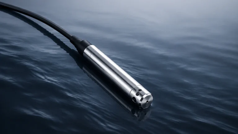
Differential Pressure Flow Meters
Differential Pressure Flow Meters
Differential pressure flow meters represent one of the most established and versatile technologies in the field of industrial fluid measurement. Widely utilized across water treatment, chemical processing, and oil and gas sectors, these instruments provide a reliable method for determining the flow rate of liquids, gases, and steam. By measuring the pressure drop across a specialized restriction in a pipe, engineers can calculate flow velocity with high precision, provided the application parameters are correctly understood.
In the context of modern industrial automation, selecting the right flow measurement technology is as critical as choosing the correct level measurement instrument. While Welk is a specialist in level measurement, understanding the broader landscape of process instrumentation—including differential pressure flow meters—is essential for comprehensive plant management and system integration. This guide explores the engineering principles, selection criteria, and installation requirements for DP flow systems.
Understanding the Measurement Principle
The operation of differential pressure flow meters is rooted in fluid mechanics, specifically Bernoulli’s principle. This principle states that for an incompressible, frictionless fluid, an increase in the speed of the fluid occurs simultaneously with a decrease in pressure or a decrease in the fluid's potential energy.
The Bernoulli Equation
In a closed pipe, when a fluid encounters a restriction (such as an orifice plate or a Venturi tube), its velocity must increase to maintain the same mass flow rate. According to Bernoulli’s equation, this increase in kinetic energy results in a corresponding drop in static pressure. The relationship is expressed as:
$$Q = k \cdot \sqrt{\Delta P}$$
Where:
* Q is the flow rate.
* k is a constant derived from the pipe diameter, the restriction size, and fluid properties (the discharge coefficient).
* ΔP is the differential pressure (the difference between the upstream pressure $P_1$ and the downstream pressure $P_2$ at the restriction).
Because the flow rate is proportional to the square root of the differential pressure, these meters typically have a limited "turndown ratio" (the ratio of maximum to minimum measurable flow) compared to ultrasonic or electromagnetic meters. However, their mechanical simplicity and lack of moving parts make them a staple in heavy industry.
Primary Flow Elements: Types and Characteristics
A differential pressure flow system consists of two main parts: the primary element, which creates the pressure drop, and the secondary element (the DP transmitter), which measures the pressure difference and converts it into an electrical signal.
1. Orifice Plates
The orifice plate is the most common primary element due to its low cost and ease of installation. It consists of a thin metal plate with a precisely machined hole (bore) placed between two flanges.
* Advantages: Low initial cost, standardized by international codes (ISO 5167), and suitable for most clean fluids.
* Disadvantages: High permanent pressure loss and susceptibility to wear or erosion over time, which affects accuracy.
2. Venturi Tubes
Venturi tubes feature a tapered inlet that constricts the flow and a flared outlet that allows the fluid to recover most of its pressure.
* Advantages: Extremely low permanent pressure loss, high accuracy, and excellent performance with fluids containing solids or slurries.
* Disadvantages: High manufacturing cost, large physical footprint, and difficult installation in existing piping.
3. Flow Nozzles
Flow nozzles are essentially a hybrid between an orifice plate and a Venturi tube. They feature a curved inlet but lack the long recovery cone of the Venturi.
* Advantages: Better pressure recovery than orifice plates and highly resistant to erosion, making them ideal for high-velocity steam applications.
* Disadvantages: More expensive than orifice plates and harder to install.
4. Pitot Tubes and Averaging Pitot Tubes
Pitot tubes measure the difference between the impact (stagnation) pressure and the static pressure at a specific point in the flow stream.
* Advantages: Minimal pressure drop and very easy to install (often via a single tap).
* Disadvantages: Sensitive to velocity profile distortions and prone to clogging in dirty fluids.
Selection Criteria for Industrial Applications
Choosing the correct differential pressure flow meter requires a detailed analysis of the process conditions. Engineers must evaluate several factors to ensure long-term reliability and accuracy.
Fluid Properties
The viscosity and density of the fluid are paramount. For highly viscous fluids, standard orifice plates may not be suitable because the Reynolds number (a dimensionless value representing the ratio of inertial forces to viscous forces) may fall below the linear range of the meter. In such cases, wedge meters or specialized Venturi tubes are preferred.
Reynolds Number (Re)
Most DP meters are designed for turbulent flow (typically $Re > 10,000$). If the flow is laminar or in the transitional zone, the discharge coefficient ($k$) becomes unstable, leading to significant measurement errors.
Permanent Pressure Loss
Every restriction in a pipe causes a loss of energy. In large-scale pumping operations, such as municipal water treatment or long-distance oil pipelines, the energy cost of overcoming the pressure drop caused by an orifice plate can be substantial over the course of a year. In these scenarios, the higher upfront cost of a Venturi tube is often justified by the energy savings.
Turndown Ratio Requirements
Standard DP meters typically offer a 3:1 or 4:1 turndown ratio. If the process requires measuring flow across a wider range (e.g., 10:1), engineers may need to use multiple transmitters with different ranges or opt for a different technology altogether.
Installation Guidelines and Best Practices
The accuracy of differential pressure flow meters is heavily dependent on the installation environment. Even the most precise DP transmitter cannot compensate for a poorly installed primary element.
Straight Pipe Runs
To ensure a fully developed and symmetrical velocity profile, DP meters require a minimum length of straight pipe both upstream and downstream of the primary element.
* Upstream: Typically 10 to 40 pipe diameters (D), depending on the presence of elbows, valves, or pumps.
* Downstream: Typically 5 diameters (D).
If space is limited, flow conditioners or straightening vanes may be installed to reduce the required straight run.
Impulse Line Orientation
Impulse lines (the small-diameter pipes connecting the primary element to the transmitter) must be installed correctly to prevent trapped air (in liquid lines) or trapped condensate (in gas lines).
* Liquid Service: The transmitter should be mounted below the pipe, and impulse lines should slope downward to the transmitter so that any gas bubbles can rise back into the main pipe.
* Gas Service: The transmitter should be mounted above the pipe, and impulse lines should slope upward so that any liquid droplets can drain back into the process.
* Steam Service: Impulse lines must include condensate pots to protect the transmitter from high temperatures.
Tapping Points
The location of the pressure taps is critical. For horizontal pipes:
* Liquid: Taps should be on the side or slightly below the centerline.
* Gas: Taps should be on the top or side of the pipe.
* Steam: Taps should be on the side of the pipe.

Comparison Table of DP Flow Elements
| Feature | Orifice Plate | Venturi Tube | Flow Nozzle | Averaging Pitot Tube |
| :— | :— | :— | :— | :— |
| Accuracy | Moderate (±1-2%) | High (±0.5-1%) | Moderate (±1%) | Low to Moderate (±1-3%) |
| Pressure Loss | High | Very Low | Moderate | Negligible |
| Cost | Low | High | Medium | Low |
| Suitability for Slurries | Poor | Excellent | Fair | Poor |
| Installation Ease | Easy | Difficult | Moderate | Very Easy |
| Maintenance | High (Wear) | Low | Low | Moderate (Clogging) |
Limitations and Operational Considerations
While differential pressure flow meters are robust, they are not without limitations. One of the primary challenges is the square-root relationship between pressure and flow. At the lower end of the flow range (e.g., below 20% of maximum flow), the differential pressure produced is very small, making it difficult for the transmitter to distinguish the signal from noise. This results in decreased accuracy at low flow rates.
Furthermore, DP meters are sensitive to changes in fluid density. Since the calculation assumes a specific density, any variation in temperature or pressure—especially in gas and steam applications—will introduce errors. To mitigate this, "multivariable" transmitters are often used, which measure static pressure and temperature alongside differential pressure to provide a real-time compensated mass flow reading.
For those managing complex industrial sites, integrating flow data with level data is essential for mass balance and inventory control. You can Review product options and application support to see how advanced instrumentation fits into your specific process architecture.
Frequently Asked Questions (FAQs)
Q: How often should an orifice plate be inspected?
A: In abrasive or corrosive services, inspection should occur every 6 to 12 months. Any rounding of the sharp upstream edge of the orifice will lead to an under-measurement of flow.
Q: Can DP flow meters measure bi-directional flow?
A: Standard orifice plates and Venturi tubes are unidirectional. However, specialized symmetrical orifice plates and bi-directional DP transmitters can be used for applications where flow direction changes.
Q: What is the impact of a clogged impulse line?
A: A clogged impulse line will cause the transmitter to show a sluggish response or a fixed, incorrect value. This is a common maintenance issue in dirty fluid applications and can be prevented with regular flushing or the use of diaphragm seals.
Q: Why is the Reynolds number important?
A: The Reynolds number determines the flow regime. DP meters are calibrated for specific regimes (usually turbulent). If the Reynolds number changes significantly due to velocity or viscosity changes, the meter's discharge coefficient changes, leading to errors.
Summary of Best Practices
To ensure the success of a differential pressure flow meter installation, follow these engineering steps:
1. Verify Fluid Conditions: Ensure the fluid is compatible with the primary element material and that the Reynolds number remains within the linear range.
2. Prioritize Straight Runs: Adhere strictly to the upstream and downstream piping requirements to avoid velocity profile distortions.
3. Select the Right Element: Use orifice plates for cost-sensitive clean liquid applications, but consider Venturi tubes for high-flow, low-pressure-loss requirements.
4. Maintain Impulse Lines: Ensure proper sloping and the use of isolation valves for easier maintenance and calibration.
5. Compensate for Density: In gas and steam applications, always include temperature and pressure compensation for accurate mass flow measurement.
By following these factual guidelines, engineers can leverage the reliability of differential pressure flow meters to achieve precise process control and optimized industrial performance. For further technical specifications and to explore complementary measurement technologies, visiting the Main Page of leading instrument providers is recommended.