Radar Level Transmitter Selection Guide
Radar Level Transmitter Selection Guide: Engineering Principles and Application Criteria
In modern industrial automation, precise level measurement is critical for inventory management, process safety, and operational efficiency. Among the various technologies available, radar-based systems have emerged as the gold standard for challenging environments. This radar level transmitter selection guide provides a technical framework for engineers and procurement professionals to evaluate, specify, and implement radar technology across diverse industrial sectors, including water treatment, chemical processing, and oil and gas.
1. Understanding Radar Measurement Principles
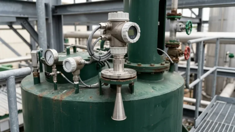
Before selecting a device, it is essential to understand how Radar Level Meters interact with the process media. Radar level transmitters utilize electromagnetic waves, typically in the microwave spectrum, to determine the distance to a product surface. Unlike ultrasonic sensors, which rely on sound waves and are sensitive to air temperature and pressure changes, radar waves travel at the speed of light and are largely unaffected by the vapor space composition.
Time of Flight (ToF)
The fundamental principle is Time of Flight. The transmitter emits a signal, which reflects off the media surface and returns to the sensor. The distance ($D$) is calculated using the formula:
$$D = \frac{c \times t}{2}$$
Where $c$ is the speed of light and $t$ is the measured transit time.
Pulse Radar vs. FMCW
There are two primary methods for processing these signals:
1. Pulse Radar: The device emits a short microwave pulse and measures the time it takes to return. This is energy-efficient and suitable for many standard liquid applications.
2. Frequency Modulated Continuous Wave (FMCW): The device emits a continuous signal with a constantly changing frequency. The difference in frequency between the emitted and received signal is proportional to the distance. FMCW offers higher accuracy and better signal-to-noise ratios, making it ideal for complex environments like solids or turbulent liquids.
2. Contact vs. Non-Contact Radar
One of the first decisions in any radar level transmitter selection guide is choosing between Guided Wave Radar (GWR) and Non-Contact (Free-Space) Radar.
Guided Wave Radar (GWR)
GWR utilizes a physical probe (cable or rod) to guide the microwave signal to the media. This technology is highly effective for:
* Low Dielectric Media: Since the energy is concentrated around the probe, it can detect surfaces with low reflectivity (e.g., oils or liquefied gases).
* Interface Measurement: GWR can measure both the total level and the interface between two liquids (e.g., oil over water).
* Internal Obstructions: Because the signal is contained, it is not affected by tank walls or internal pipes.
Non-Contact Radar
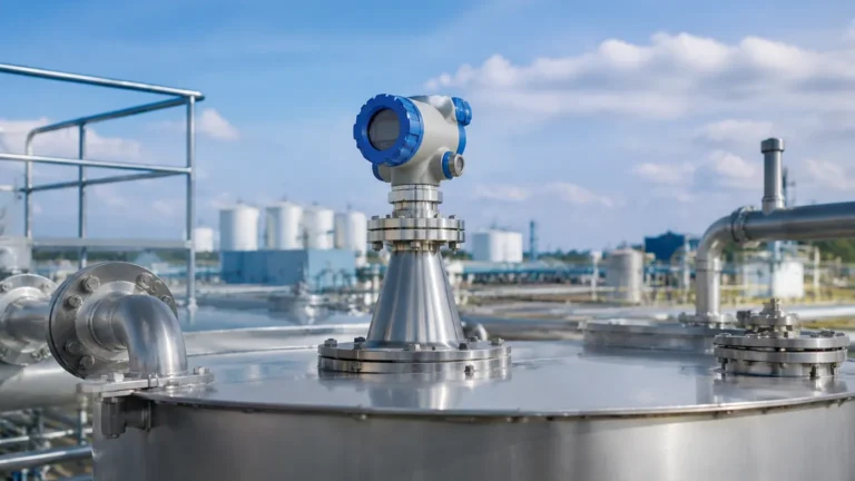
Non-contact radar emits signals through the air. It is preferred for:
* Corrosive or Hygienic Media: There is no physical contact with the product, reducing maintenance and contamination risks.
* High Temperature/Pressure: Sensors can be isolated from the process via PTFE or ceramic windows.
* Aggressive Solids: Avoids mechanical stress on probes caused by heavy bulk solids.
3. Key Selection Criteria
Selecting the right instrument requires a detailed analysis of the process conditions. Use the following parameters as a checklist.
Dielectric Constant ($ε_r$)
The dielectric constant of the media determines how much signal is reflected. Water has a high $ε_r$ (~80) and is easy to measure. Hydrocarbons often have low $ε_r$ (1.7 to 2.5), requiring high-sensitivity transmitters or GWR probes.
Process Environment
* Temperature and Pressure: Standard units handle up to 150°C (302°F), but specialized high-temperature versions can withstand over 450°C (842°F).
* Vapor and Foam: Heavy steam or thick, absorbing foam can attenuate radar signals. In these cases, lower frequency radar (6GHz) or GWR may be necessary to penetrate the surface layer.
* Agitation and Turbulence: Rapidly moving surfaces require faster update rates and sophisticated software algorithms to filter out "noise."
Vessel Geometry
The height of the vessel determines the required range. While some radar meters can measure up to 100 meters (328 ft), the presence of internal agitators, heating coils, or ladders requires a narrow beam angle to avoid false reflections.
4. Frequency Selection: 6GHz, 26GHz, and 80GHz
The frequency of the radar signal significantly impacts its performance and beam characteristics.
| Frequency | Beam Angle | Best Use Case |
| :— | :— | :— |
| 6 GHz (C-Band) | Wide (approx. 20-30°) | Applications with heavy steam, foam, or condensation. High penetration capability. |
| 26 GHz (K-Band) | Medium (approx. 8-12°) | General-purpose liquid and solid measurement in medium-sized tanks. |
| 80 GHz (W-Band) | Narrow (approx. 3-4°) | Small vessels, tall nozzles, and high-precision requirements. Excellent for avoiding internal obstructions. |
5. Installation Considerations and Best Practices
Even the most advanced radar level transmitter will fail if installed incorrectly. Adhering to engineering best practices ensures long-term reliability.
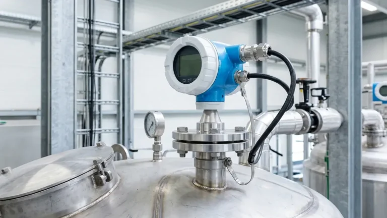
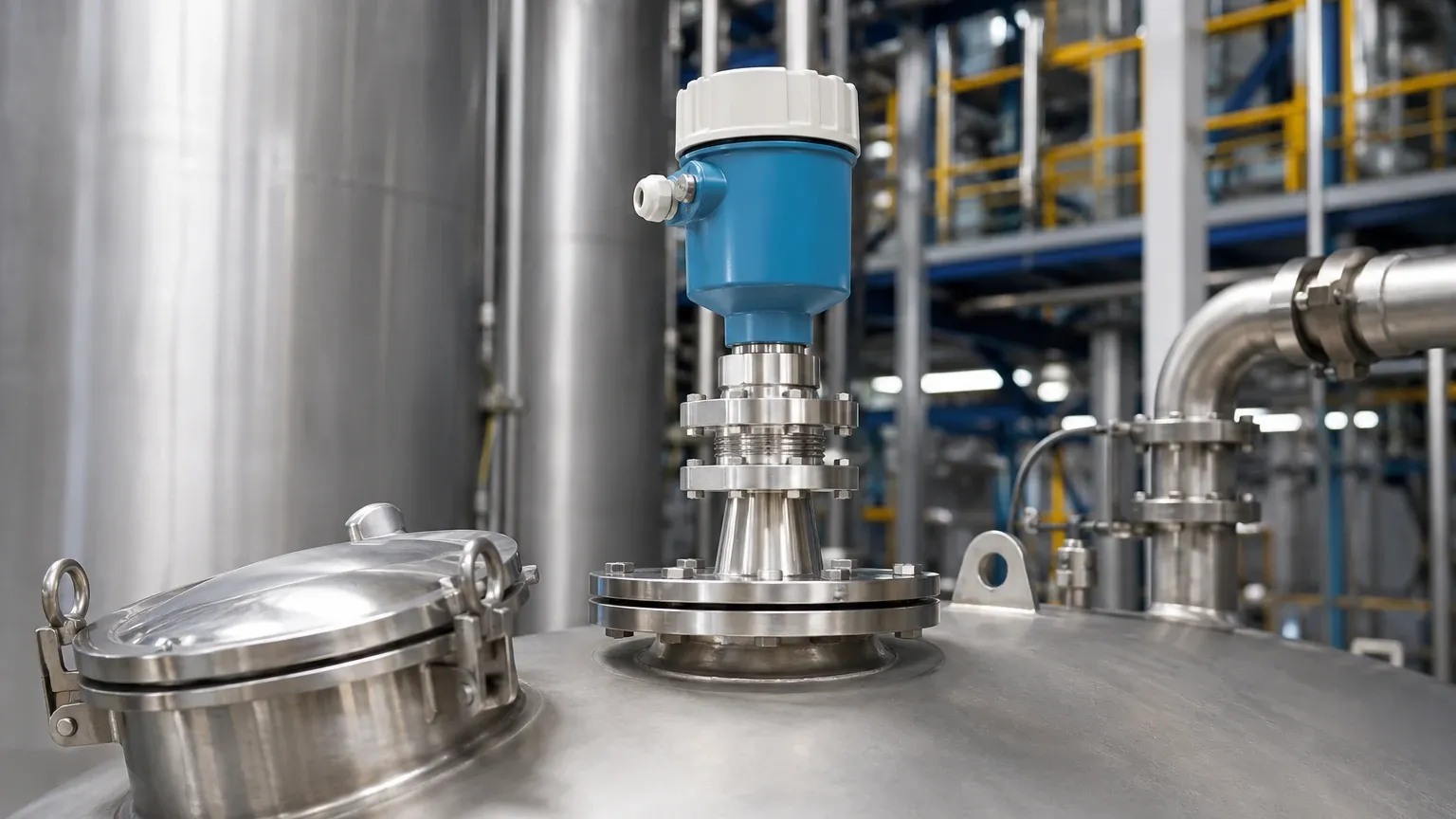
1. Nozzle Height and Diameter: The nozzle should be as short as possible. If a long nozzle is required, an 80GHz transmitter is recommended due to its narrow beam, which prevents the signal from reflecting off the nozzle walls.
2. Avoid the Center: Never install a non-contact radar in the exact center of a domed tank. This can cause multiple reflections to converge, resulting in signal interference.
3. Dead Zones (Blocking Distance): Every radar has a minimum detection distance near the antenna (typically 50mm to 300mm). Ensure the maximum fill level does not enter this zone.
4. Beam Path Clearance: Ensure the "cone" of the radar signal does not intersect with inflow streams, agitator blades, or wall supports.
6. Practical Selection Table for Industrial Applications
| Application | Recommended Technology | Rationale |
| :— | :— | :— |
| Municipal Water Tank | 80GHz Non-Contact | High accuracy, maintenance-free, easy installation on concrete or plastic tanks. |
| Oil/Water Interface | Guided Wave Radar (GWR) | Able to penetrate the upper layer to detect the secondary liquid level. |
| Acid Storage (Corrosive) | Non-Contact with PTFE Flange | Prevents chemical attack on the sensor; no moving parts to corrode. |
| Cement Silo (Dusty) | 80GHz FMCW Radar | High frequency and FMCW processing handle signal attenuation from heavy dust. |
| High-Pressure Boiler | GWR with Steam Compensation | Physical probe ensures signal stability in saturated steam environments. |
7. Limitations of Radar Technology
While highly versatile, radar is not a universal solution. Engineers should be aware of the following limitations:
* Extremely Low Dielectrics: Media with $ε_r < 1.4$ (such as liquid nitrogen) may not reflect enough energy for standard non-contact radar.
* Conductive Foam: While radar can see through some foam, highly conductive, thick foam can act as a false surface or completely absorb the signal.
* Vacuum Limitations: While the signal travels through a vacuum, the mechanical seals and gaskets of the transmitter must be rated for vacuum service to prevent leakage into the electronics.
8. Frequently Asked Questions (FAQs)
Q: Can radar measure solids like grain or plastic pellets?
A: Yes. However, solids often have an angle of repose (sloped surface). High-frequency 80GHz radar is preferred here because its narrow beam can target a specific point on the slope more effectively than lower frequencies.
Q: Does the color or transparency of the liquid affect the measurement?
A: No. Radar relies on the electrical properties (dielectric constant) and not optical properties. It works perfectly on clear, opaque, or dark liquids.
Q: How often does a radar level transmitter need calibration?
A: Radar is a solid-state technology with no moving parts. In most stable applications, it does not drift. Periodic "verification" (comparing the reading to a manual dip tape) is recommended annually, but full recalibration is rarely necessary unless the process media changes significantly.
Q: Is radar safe for explosive environments?
A: Yes, most industrial radar transmitters are available with ATEX, IECEx, or FM certifications for use in intrinsically safe (Ex ia) or explosion-proof (Ex d) zones.
Conclusion
Selecting the appropriate radar level transmitter involves balancing technical requirements with cost-effectiveness. By considering the dielectric constant, vessel geometry, and the specific advantages of different frequencies, engineers can implement a solution that provides years of maintenance-free service. For complex applications, consulting with a professional manufacturer like Welk ensures that the selected Radar Level Meters are optimized for the specific chemical and physical properties of the process media. Following this radar level transmitter selection guide will mitigate common installation risks and ensure high-precision data for industrial automation systems.