Radar Level Sensor 80 GHz
Radar Level Sensor 80 GHz
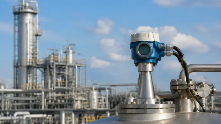
In the field of industrial process automation, the demand for higher precision, smaller process connections, and more reliable performance in challenging environments has driven the evolution of radar technology. The transition from traditional 6 GHz and 26 GHz systems to the radar level sensor 80 GHz represents a significant milestone in non-contact level measurement. This high-frequency technology, utilizing Frequency Modulated Continuous Wave (FMCW) principles, offers distinct advantages for both liquid and solid applications where accuracy and signal reliability are paramount.
For engineers and procurement professionals, understanding the technical nuances of 80 GHz systems is essential for optimizing process control. These Radar Level Meters provide a focused measurement beam that minimizes interference from internal tank structures, making them the preferred choice for modern industrial facilities.
Understanding the 80 GHz FMCW Principle
Unlike older pulse-based radar systems, the 80 GHz radar level sensor typically operates on the Frequency Modulated Continuous Wave (FMCW) principle. In this method, the sensor emits a continuous high-frequency signal whose frequency increases linearly over time, creating a "sweep" or "chirp."
When the signal reaches the surface of the medium (liquid or solid), it is reflected back to the antenna. Because the transmitter is constantly changing the frequency of the emitted signal, there is a measurable difference between the frequency currently being transmitted and the frequency of the echo that has just returned. This frequency difference ($Δf$) is directly proportional to the time of flight, and therefore, the distance to the material surface.
At 80 GHz, the bandwidth of this frequency sweep is significantly wider than at 26 GHz. A wider bandwidth allows for a much higher range resolution. In practical terms, this means the sensor can distinguish between the material surface and nearby obstacles (such as agitators or weld seams) with far greater clarity. This high-resolution signal processing is what allows 80 GHz sensors to maintain a measurement accuracy of often ±1 mm (0.04 inches) over ranges exceeding 30 meters (98 feet).
Key Advantages of High-Frequency Radar Level Meters
The shift to 80 GHz technology offers several technical benefits that solve long-standing issues in level instrumentation:
1. Narrow Beam Angle
The beam angle is inversely proportional to the frequency and the antenna diameter. At 80 GHz, the wavelength is approximately 3.75 mm, which is much shorter than the 11 mm wavelength of 26 GHz radar. This allows for a very narrow beam angle—often as small as 3° to 4°—even with a small antenna size. A narrow beam ensures that the radar energy is focused on the product surface rather than reflecting off tank walls, ladders, or heating coils.
2. Smaller Process Connections
Because high-frequency signals require smaller antennas to achieve a narrow beam, 80 GHz sensors can be installed on very small process connections. It is common to find 80 GHz units with 1-inch or 1.5-inch threaded connections that outperform older 26 GHz units requiring 4-inch or 6-inch flanges. This reduces installation costs and allows for measurement in small vessels or bypass pipes.
3. Superior Performance in Dust and Vapor
While it was once thought that higher frequencies would suffer more from signal attenuation in dusty environments, 80 GHz technology has proven highly effective in solids applications. The high dynamic range of modern 80 GHz chips allows the sensor to track the "true" echo even through dense dust clouds in grain silos or cement bunkers. Furthermore, the narrow beam avoids the "noise" typically generated by reflections from the side walls of tall, narrow silos.
Technical Comparison: 80 GHz vs. 26 GHz Technology
When selecting a radar level sensor 80 GHz, it is helpful to compare its performance characteristics against the previous industry standard, 26 GHz.
| Feature | 26 GHz Radar | 80 GHz Radar |
| :— | :— | :— |
| Wavelength | ~11 mm | ~3.75 mm |
| Typical Beam Angle | 8° to 15° | 3° to 6° |
| Accuracy | ±3 mm to ±5 mm | ±1 mm |
| Min. Process Connection | 2" to 3" Flange | 3/4" Thread / 1" Flange |
| Max. Measuring Range | Up to 30m – 70m | Up to 120m (393 ft) |
| Signal Sensitivity | Moderate | Very High |
| Obstacle Immunity | Requires mapping | Naturally avoids most obstacles |
Selection Criteria for Industrial Applications
Choosing the right radar level meter requires an evaluation of the process media and the physical environment. International buyers should confirm the following parameters before procurement:
Dielectric Constant (εr)
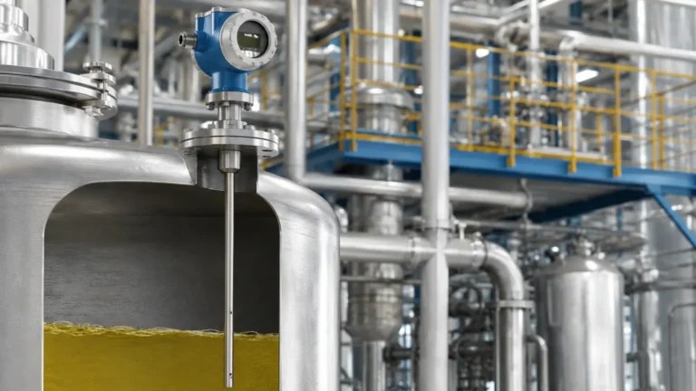
The dielectric constant of the medium determines how much energy is reflected back to the sensor. High-frequency 80 GHz sensors have excellent sensitivity, allowing them to measure materials with very low dielectric constants (εr > 1.4), such as plastic pellets or certain hydrocarbons. However, for extremely low εr materials, a guided wave radar or a specialized high-sensitivity 80 GHz unit may be required.
Measuring Range and Surface Conditions
80 GHz sensors are capable of measuring distances up to 120 meters (393 feet). However, the surface condition matters. A turbulent liquid surface or a sloped solid surface will scatter the radar signal. The high signal-to-noise ratio of 80 GHz technology helps mitigate this, but it is still vital to select an antenna type (e.g., lens antenna) suited for the specific surface.
Temperature and Pressure Extremes
Industrial processes often involve high temperatures (up to 250°C / 482°F) and high pressures (up to 40 bar / 580 psi). Ensure the sensor's process seal (typically PTFE, PEEK, or Ceramic) is compatible with the chemical nature and the thermal profile of the medium.
Installation Guidelines and Best Practices
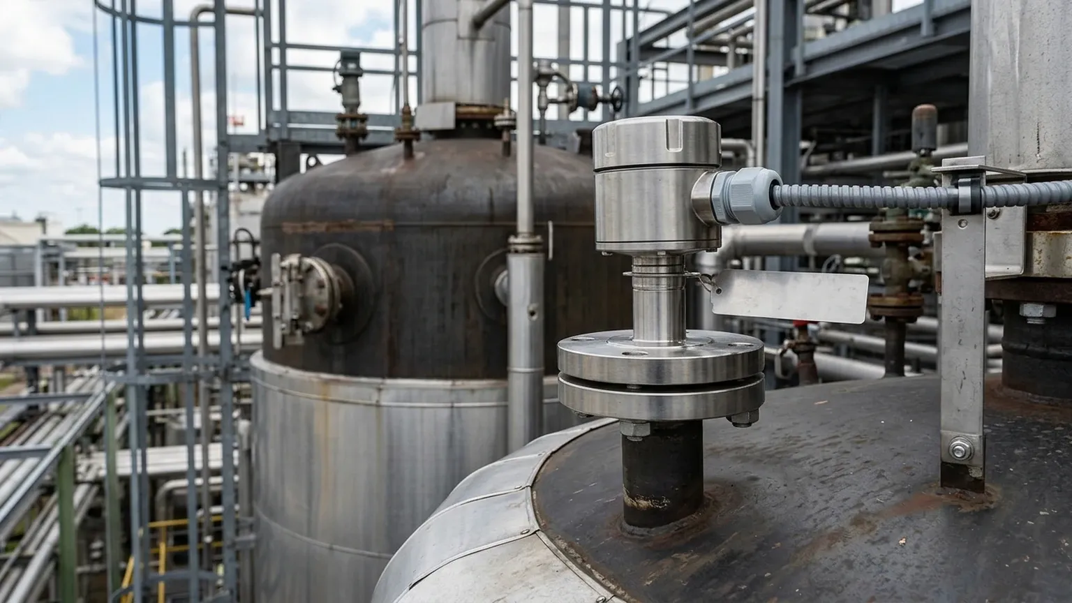
Proper installation is critical to ensure the longevity and accuracy of a radar level sensor 80 GHz. Even with a narrow beam, certain geometric rules apply:
1. Avoid the Center: Do not install the sensor in the exact center of a dome-roof tank, as this can lead to multiple reflections that interfere with the signal. Position the sensor at approximately 1/3 of the tank radius from the wall.
2. Nozzle Height and Diameter: The antenna should ideally extend slightly beyond the bottom of the mounting nozzle to prevent "ringing" or internal nozzle reflections. If the nozzle is very long, ensure the beam angle does not intersect the nozzle wall before exiting.
3. Vertical Alignment: The sensor must be mounted perpendicular to the product surface. For solids, where the material forms a cone, an adjustable flange (aiming device) is often used to direct the beam toward the center of the cone to maximize signal return.
4. Obstruction Clearance: While the 3° beam is narrow, it still spreads over distance. At 20 meters (65 feet), a 3° beam has a diameter of approximately 1.05 meters (3.4 feet). Ensure no structural beams or pipes enter this cone.
Limitations and Environmental Considerations
Despite the robustness of 80 GHz technology, certain conditions present challenges:
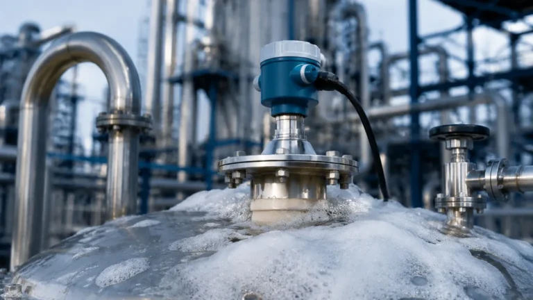
* Heavy Foam: Extremely dense, thick foam can absorb the radar signal entirely, preventing an echo from reaching the liquid surface. In such cases, 80 GHz may perform better than lower frequencies, but measurement is not always guaranteed.
* Condensation and Buildup: While many 80 GHz sensors feature a flush-mounted PTFE lens antenna that resists buildup, heavy condensation or viscous coating on the antenna face can attenuate the signal. Some models include integrated air purging connections to keep the lens clean.
* Extreme Steam: Very high-pressure saturated steam can change the dielectric constant of the gas space above the liquid, slightly affecting the speed of the radar wave and introducing a small measurement error. For high-pressure boiler drums, specialized compensation may be needed.
Frequently Asked Questions (FAQ)
Q: Can 80 GHz radar measure through plastic tank walls?
A: Yes, because plastic has a low dielectric constant, the 80 GHz signal can penetrate the wall of a plastic (PE/PP) or fiberglass tank. This allows for non-invasive measurement where the sensor is mounted outside the tank, looking through the top.
Q: Is 80 GHz better than Ultrasonic sensors for water treatment?
A: Generally, yes. Radar is unaffected by air temperature fluctuations, wind, or surface vapors, which often cause errors in ultrasonic sensors. With the decreasing cost of 80 GHz technology, it is becoming the standard even in water and wastewater applications.
Q: Does 80 GHz radar require frequent calibration?
A: No. Radar level meters are solid-state devices with no moving parts. Once calibrated to the tank height during commissioning, they typically do not drift. Periodic verification is recommended according to local safety or quality standards.
Conclusion
The radar level sensor 80 GHz has redefined the boundaries of non-contact level measurement. By offering a narrow beam, high precision, and the ability to operate through small process connections, it provides a versatile solution for the chemical, oil and gas, and bulk solids industries. When selecting equipment, engineers should prioritize the dielectric properties of the medium and the physical constraints of the vessel to leverage the full potential of high-frequency FMCW technology. For professional-grade instrumentation and customized OEM solutions, Welk continues to provide robust Radar Level Meters designed for the rigors of modern industrial automation.